Yuriy Zachinyaev,
Konstantin Rumyancev
Southern Federal University, Russia
Fiber-optic Based Generator of
Nanosecond Linear
Frequency Modulated Signals
Several techniques to generate the LFM (chirp) signal
have been proposed over the past few decades. Generally all the techniques can
be categorized into 3 types: analog generator approach, dispersive delay line
approach (surface acoustic wave (SAW) generators) and digital approach [1, 2].
Analog approach involves analog radio technical
methods of producing LFM chirps using controlled LC-generators, phase
modulators, dispersive SAW time delay lines. Generating high-frequency chirps
(1-20 GHz) involves such devices as backward-wave tubes, reflex klystrons and
yttrium iron garnet (YIG) generators.
Unlike analog chirp generator the properties of the
digitally generated waveform (type of modulation, start and stop frequency,
waveform output duration) can be configured easily by changing the firmware and
memory contents of the digital generator. Two of the most popular digital chirp
generator architectures are the Memory-based architecture and Direct Digital
Synthesizer (DDS) architecture. At the same time, digital method has some
serious disadvantages: the necessity of using additional devices for frequency
mixing and inability to produce large time-bandwidth signals.
The minimal chirp pulse width is provided by SAW
devices and backward-wave tubes based generator while the chirp rate is maximum
in backward-wave tubes based generators. Such values make LFM signals hardly
usable in such applications as radio tomography, underground location and high
speed secure communications since having large dead zone.
Impossibility of using traditional methods for
high-speed generating and processing of UWB signals including the LFM signals
makes it necessary to use optical methods of data processing including the
application of fiber-optic structures for this purpose. The appropriateness of
such structures application is due to the properties of optical fibers:
dramatically low light signals power loss (less than 0.2 dB/km), broad
bandwidth per unit length (over 500 GHz·km), excellent electromagnetic
compatibility with any electrical and radio equipment and perfect galvanic
isolation from him, high noise immunity, small dimensions, weight and
topological flexibility [4].
The applications of optical fibers in the purposes of
radio signals generating and processing were revealed when the latter came to
be regarded as a key element of optical signal delay lines. It was shown that
the potential of optical fiber as an optical delay line for light signals
modulated with the radio frequency are out of competition compared with
well-known in radio physics devices in such critical parameters as normalized
modulated light signal loss and time-bandwidth product. According to these
facts, a new method of the LFM signals generating is suggested. Architecture
for this method is shown on the Fig. 1.
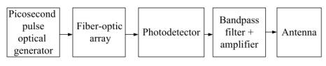
Figure 1. Architecture of the optical LFM generator [4,7]
Picosecond pulse optical generator produces a short pulse of certain
amplitude and submits it to the fiber-optic array that consists of optical
splitter, optical coupler and the number of binary optical structures and optical
delay lines (Fig.2.а).
Figure 2. Architecture of Fiber-optic array (a) and architecture of the
Binary fiber-optic structure (b) [4, 5, 7]
Every binary optical structure in array produces K copies of the input
signal ![]() with pulse width
with pulse width ![]() and repetition period
and repetition period
![]() :
:
![]() . (1)
. (1)
Binary fiber-optic structures from all other optical
structures ensure a high level of identity of copies and a low consumption of
fiber (Fig. 2.b).
Thus the fiber-optic array produces N⋅K copies of the input picosecond impulse, where N - number of Binary
optical structures in array. Structures in array differ by the repetition
period of the copies ![]() that can be
calculated for the n-th structure with [5]
that can be
calculated for the n-th structure with [5]
 (2)
(2)
where ![]() is initial frequency
of LFM signal,
is initial frequency
of LFM signal, ![]() - chirp
rate. Number of copies
- chirp
rate. Number of copies ![]() generated by each structure can be found with
generated by each structure can be found with
 .
(3)
.
(3)
Finally the number of
structures in array N is calculated with
 , (4)
, (4)
where ![]() - the
duration of the LFM signal,
- the
duration of the LFM signal, ![]() -
central frequency of LFM signal.
-
central frequency of LFM signal.
From the output of the Binary optical structures array
a sequence of ![]() optical pulses is fed to the photo receiver
module that converts the optical signal into electrical. Finally, the first
harmonic of the resulted signal is allocated using a band pass filter. After
additional filtering and amplification, signal is radiated by antenna. The
results of computer modeling for the LFM signal with
optical pulses is fed to the photo receiver
module that converts the optical signal into electrical. Finally, the first
harmonic of the resulted signal is allocated using a band pass filter. After
additional filtering and amplification, signal is radiated by antenna. The
results of computer modeling for the LFM signal with ![]() = 9,25 ns,
= 9,25 ns, ![]() = 1081 GHz/µs are shown on the Fig. 3 ((a) –
spectral density, (b) – signal on the correlator output).
= 1081 GHz/µs are shown on the Fig. 3 ((a) –
spectral density, (b) – signal on the correlator output).
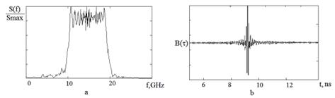
Figure 3. Results of optical chirp generation modeling
The suggested method allows producing LFM signals with
duration from 2 ns and chirp rate up to 3000 GHz/µs [5]. For evaluation of the
conditions of the functioning of the fiber-optic based chirp generator a
simulation was performed using MATLAB software. The minimum of autocorrelation
function side lobe peak level has been chosen as criteria for evaluation of the
chirp signal quality. Simulation was held with the following parameters: chirp
duration ![]() = 2.2 ns, the central frequency of the chirp
signal
= 2.2 ns, the central frequency of the chirp
signal ![]() = 10.1 GHz; frequency deviation
= 10.1 GHz; frequency deviation ![]() =5.89 GHz; the
required power output
=5.89 GHz; the
required power output ![]() = 100 mW; average
output optical power of optical generator
= 100 mW; average
output optical power of optical generator ![]() = 10 mW; the signal /
noise ratio at the output of the generator SNR = 50 dB.
= 10 mW; the signal /
noise ratio at the output of the generator SNR = 50 dB.
Measured pulse width is 2.1 ns (minus 3 dB level)
which is 4.5 % different from the value provided by the design. Output power ![]() = 103 mW, which is
2.9 % different from the value provided by the design.
= 103 mW, which is
2.9 % different from the value provided by the design.
Analysis of the dependence of the ambient temperature
fluctuations on the parameters of the fiber-optic based chirp generator with
zero optical fiber length manufacturing intolerance was performed using the
following parameters: optical fiber length manufacturing intolerance ![]() =0, the ambient
temperature fluctuation range
=0, the ambient
temperature fluctuation range ![]() from -60 to 60 ° C
with steps of 5 ° C The results of simulation in graphic form for the generator
without amplitude weighting (a) and with amplitude weighting (b) are shown on
Fig. 4.
from -60 to 60 ° C
with steps of 5 ° C The results of simulation in graphic form for the generator
without amplitude weighting (a) and with amplitude weighting (b) are shown on
Fig. 4.
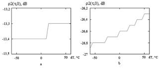
Figure 4. The value of autocorrelation sidelobe peaks depending on the
ambient temperature fluctuations
As shown on Fig.4 for the chirp signal with pulse
width of 2.2 ns according to above specified conditions temperature
fluctuations have little effect on the correlation properties of chirp. For
generator without amplitude weighting slight increase in sidelobe peaks values
(0.1 dB) occurs in cases when the ambient temperature raises by more than 15 °
C (above 42 ° C) that if necessary requires additional cooling. In case of
reducing the ambient temperature level the autocorrelation sidelobe peak values
remain unchanged. For generator with amplitude weighting slight increase in
sidelobes (0.1 dB) occurs in cases when the ambient temperature raises by more
than 20 ° C (above 47 ° C), and 0.3 dB when the ambient temperature raises by
more than 23 ° C. At the same time reducing the ambient temperature leads to
reduction of the level of sidelobe peak values by 0.3 dB (at ![]() = 60 ° C).
= 60 ° C).
Analysis of the influence of the optical fiber length
manufacturing intolerance on the parameters of the fiber-optic based chirp
generator with zero ambient temperature fluctuations was performed using the
following parameters: ambient temperature fluctuation value ![]() = 0° C; manufacturing
error range is in -1 to 1 mm diapason with a variable pitch.
= 0° C; manufacturing
error range is in -1 to 1 mm diapason with a variable pitch.
The results of simulation in graphic form for the
generator without amplitude weighting (a) and with amplitude weighting (b) are
shown on Fig.5.
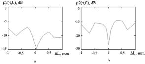
Figure 5. The value of autocorrelation sidelobe peaks depending on the
optical fiber length manufacturing intolerance
As can be seen from Fig.5 the increase of manufacturing
inaccuracies leads to the increase of the sidelobe peak values. For different
cases of amplitude weighting application the shape of curves is similar with
the difference in the value of the sidelobes.
The work was
performed as part of the state task of the Ministry of Education and Science of
the Russian higher education institutions in terms of scientific research.
Project № 213.01-11 / 2014-9.
References:
1. Kochemasov V. N., Belov L. A., Okoneshnikov V. S. Formirovanie
signalov s linejnoj chastotnoj moduljaciej. M.: Radio i svjaz', 1983. 192 p.
2. Merrill I. Skolnik. Radar Handbook (2nd Edition). - McGraw-Hill,
1990. 1220 p.
3. Zachinyaev Y. V. Analiz i klassifikacija formirovatelej
linejno-chastotno-modulirovannyh radiosignalov c tochki zrenija umen'shenija
dlitel'nosti formiruemyh signalov // Sovremennye problemy nauki i obrazovanija.
2012. № 5. URL: http://www.science-education.ru/105-7173 (date of submission:
12.10.2013)
4. Zachinyaev Y. V., Rumyantsev K.E. Assessment of the influence of
physical factors on the operational features of the linear frequency shift
keying signal generator based on the fiber optic structures // Izvestija
vysshih uchebnyh zavedenij Rossii. Radiojelektronika, 2012. № 4. p. 91-101
5. Kukujashnyj A.V. Osobennosti formirovanija LChM signalov s
ispol'zovaniem volokonno-opticheskih struktur // Informacionnoe protivodejstvie
terrorizmu. 2007. №9. p. 75-88.
6. Rumyantsev K.E., Gorbunov A.V. Dinamicheskie zapominajushhie
ustrojstva na osnove binarnyh volokonno-opticheskih struktur // Radiotehnika.
2002. №12. p. 73-80
7. Zachinyaev Y. V., Rumyantsev K.E., Kukujashnyj A.V. Formirovanie
nanosekundnyh LChM-radiosignalov na volokonno-opticheskih strukturah //
Jelektrotehnicheskie i informacionnye sistemy i kompleksy. 2011. P.7, №3. p.
32-38.