Trunov V.S, Mochalov A.S,
Koltsova E.A.
Ivanovo State Power
Engineering University
DEVELOPMENT OF APPARATUS AND
SOFTWARE COMPLEX FOR SCANNING OF THREE-DIMENSIONAL OBJECTS
The paper deals with scanning of 3-dimensional object techniques. As 3D
modeling has become popular in engineering and designing, the issue of
obtaining 3D computer model from an existing object is of great importance. Some
complicated objects contain an enormous amount of smaller details and their
modeling can take quite long. Therefore, this process requires automation.
This research aims at developing a device which is able to scan 3D
objects and obtain a computer model represented as a point cloud for further
transformations into well-known editors' formats. This device is expected to meet next
requirements:
1. The computer model should be precise, it is to exactly
copy the object (all the complex parts it consists of must be reflected in the
model).
2. The device software is required to be open-source and
free. Documentation of how to deploy and use it is expected to be
published.
3. All the calculations this device performs are to be
sped up to minimize the time of scanning.
4. The device is required to be as cheap as possible, it is
to contain only the elements which can be easily purchased. Everyone should be enabled
to assemble such a device.
To achieve the aim, the following research methodologies were employed:
1. Experimental study for improving the main procedure of
model obtaining and speeding up the calculations.
2. Correlation study to determine the relationship
between the quality of obtained model and device parameters such as the frequency
of step motor and the angle between the camera and the source of laser beam.
Device
hardware and components
The list of
included components is represented below.
1. Arduino Uno Computing platform.
2. Nema 23' Stepper Motor.
3. ULN2003 Unipolar stepper motor driver on
microcircuits.
4. Power Supply of 12v 300w.
5. 800x600 Web-camera.
6. The case of a cubic form with a side of 0.5 m and a
rotating disk (platform).
7. 22' LED screen.
The schematic
diagram of the device is shown in Figure 1.
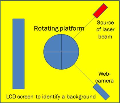
Fig.
1. Schematic diagram of the device.
For object scanning it was decided to put the camera and the source of
laser beam statically (they aren't moving throughout the whole scanning process)
and to move the object around the axis of rotation. The vertical laser beam
passing through the middle of the rotating platform falls on the object
outline. The web-camera takes pictures of that object with the laser beam on
its surface. The platform keeps rotating and the camera keeps taking pictures
until the whole object surface is handled. Device components are put in the
special box with the walls covered with light-absorbing material to absorb the
laser and prevent its reflection.
Device
software
The
software presents the mathematical solutions listed below.
1. Laser recognition.
2. Distance measuring of the laser beam.
3. Plane transformation (from 2D plane to 3D).
4. Object representation in computer memory.
Let us consider each item in more detail.
Laser
recognition
The laser line should be the brightest in the picture,
the color of it should be known. There is a way to select a laser line from an
image by decomposing the image into RGB streams. The algorithm has been
developed with the help of C++ and OpenCV framework.
In figures 2-3 the experiment of laser recognition is presented.
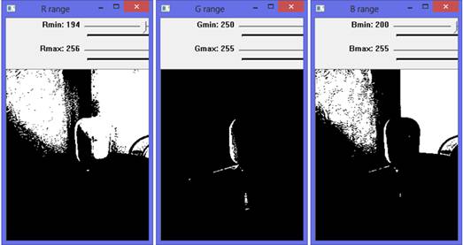
Fig. 2. Stream decomposition
of an image. Threshold determining for each stream.

Fig. 3. Logical
multiplication of streaming images and receipt of recognized laser line.
Distance measuring of the
laser beam
As the camera and the source of laser beam are situated
at an angle, the camera takes pictures of distorted laser line. Therefore, it
is necessary to calculate the precise distance to the laser beam. The issue is
presented in Figure 4.
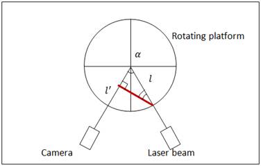
Fig. 4. The issue of laser
beam distortion.
The line ![]() (red line) is a
line the camera views,
(red line) is a
line the camera views, ![]() is a precise
one. To calculate
is a precise
one. To calculate ![]() it is necessary
to apply the following formula:
it is necessary
to apply the following formula:
Plane transformation (from 2D to 3D)
The stepper motor rotates the object at 1°. As a
result, 360 two-dimensional planes are obtained (the z coordinate is zero). To
set the z coordinate, the following conversion should be applied:
 ,
,
where ![]() ,
, ![]() ,
, ![]() are new
coordinate values;
are new
coordinate values;
![]() ,
, ![]() - coordinates
of laser points;
- coordinates
of laser points;
![]() - coordinate of
object rotation axis;
- coordinate of
object rotation axis;
![]() - angle of rotation around
the axis. If the rotation angle of the stepping motor is 1°,
- angle of rotation around
the axis. If the rotation angle of the stepping motor is 1°, ![]() equals to the number of current plane in 360
two-dimensional plane list.
equals to the number of current plane in 360
two-dimensional plane list.
Object
representation in computer memory
It has been decided to represent the object model in computer memory as
a point cloud. In other words, the model is saved in the memory as a list of
point coordinates. The point cloud allows converting to well-known editors'
formats (for instance, AutoCAD). To prove the correctness of a point cloud
which looks like the scanned object surface it was decided to build its
axonometric projection. The transformation is performed due to the
multiplication of the coordinates matrix by the transformation matrix presented
below:
In figure 5, the models of scanned white-out bottles are represented.
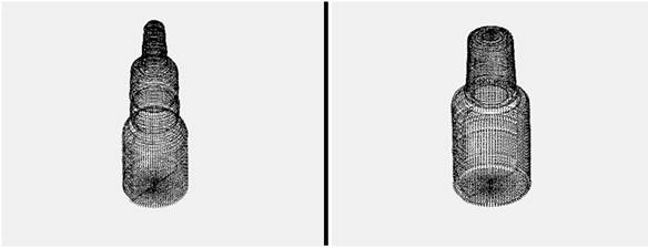
Fig. 5. Models of scanned white-out bottles
To summarise, all the goals of the study have
been achieved. As we have seen, the 3D scanning device has been assembled and
tested with several objects with all obtained models being highly precise. The
cost of the device is approximately $100, which is relatively inexpensive. The
key findings of this research have already been published in some scientific
journals in Russia. The device has practical applications with a lot of
positive feedback.
The current research contributes substantially to the objects copying
techniques. It will prospectively allow developing and assembling the copying
object device in the future.