MODELLING FRACTURING IN SHALES WITH FLUID ROCK INTERACTIONS
Aibol
NUSSIPKOZHAYEV[1], Jean-Jacques Royer[2], Murat BAIMUHAMETOV1
[1] Kazakh National Technical University after
K.Satpayev
2
∗Universit´e
de Lorraine UdL, CNRS-GeoRessources (UMR7359), ENSG-INPL, gOcad-ASGA,
Vandoeuvre, France.
Abstract
With the last
advances in uranium mining such as In-situ leaching technology the
implementation of this technology into other ore mining fields nowadays is
possible.
More exactly
it comes to the application of above mentioned technology to the copper mine
sites. This work focuses on the
creation of the structural model on gOcad of
the testing area at the Rudna mine site and on the implementation of a
hydraulic fracturing process to increase the in-situ permeability. The
hydraulic fracturing was performed using a wizard developed in the gOcad
environment. In-situ recover methods –
an alternative way to produce metals, were explained. The rock elastic
properties were estimated from laboratory assays performed on rock samples,
especially Vp and Vs seismic, density and
porosity. These values were interpolated in the grid model and used to simulate
the fracturing. The report shows simulation results using the gOcad software.
Permeability increases with injection pressure after fracturing. A predictive
cubic law relating the fractured volume against injection pressure was
proposed.
Keywords: Hydraulic fracturing, In-situ recovery, copper,
geomodeling, rock mechanics, rock elastic properties, seismic wave,
permeability
Introduction
The Polish
sediment-hosted Kupferschiefer deposit is a world-class polymetallic deposit.
It extends across North-central Europe from North-Westernmost Belorussia to
Northern Ireland, along an east-westerly belt of more than 1.500 km (Vaughan et
al., 1989). Today this World Class deposit, exploited in the South-western of
Poland by KGHM Polska Miedź S.A. (Lubin, Sieroszowice-Polkowice, and Rudna
and Glogów-Glęboki-Przemysłowy mines), is placed among one of
the main Cu-Ag deposits in the World1 (~ 2% Cu and ~ 2 Oz/t Ag in over 1 Gt
bearing metals ore 2). Lead, zinc, gold, PGE, and some critical raw materials
for the EU (2011), such as rhenium, have also economic importance (KGHM, 2011).
The copper production of Poland represents half of the total copper production
in Europe (or a quarter of the total European copper consumption).
Hydraulic fracturing
implemented to the model with the view to test the in-situ mining or in-situ
recovery (ISR) method. This involves drilling of injection and recovery wells
to dissolve the deposit underground and recover the copper. Sulphuric acid is
injected using the injection well. Pumping from the recovery wells drives the
acid from central injection well to the recovery well where it is pumped back
to the surface for processing. As the acid moves through the ore body along the
natural fractures system it dissolves the oxide copper within the fractures
system.
General information about testing area
The Rudna
mine is the largest copper ore mine in Europe and one of the largest deep
copper ore mines in the world.
Rudna Mine is located in Lower Silesia, north of Polkowice city. The
mine extracts mostly “Rudna”
deposit, but it also develop and exploit parts of “Sieroszowice” and “Głogów
Głęboki-Przemysłowy” deposits. Industrial
resources of Rudna Mine (according to state on 31.12.2013) in three operated
deposits are 449 million Mg of copper ore. Average grade of copper amounts to
1,95 %, average grade of silver – 59g/Mg.
Among the Polish copper deposits operated by KGHM, Rudna deposit stands
out the thickest orebody - up to even over a dozen meters; average thickness of
Rudna deposit is over 4 meters nowadays and over 70% of resource is over 3
meters thick. In Rudna deposit the dominant part of ore is sandstone ores –
around 80% of resources, carbonate ores represent approximately 15% and
Copper-bearing shale (Kupferschiefer) only 5% of total deposit mass.
Copper-bearing Shale (Kupferschiefer) contain the highest grade of copper
– over 6% of Cu. The depth of copper orebody in Rudna deposit range from 844 m
up to 1250 m in depth, and Głogów
Głęboki-Przemysłowy deposit is up to 1385 m in depth.
Geological setting of the Kupferschiefer
The sedimentary
formation of Kupferschiefer (literally copper shale) extends over the northern
Europe on more than 600.000 km2 (Blundell et al., 2003). The genesis of
Kupferschiefer is related to the eustatic variations of the Zechstein Sea at
the end of Permian. It is composed of a thin (< 1m) shale layer containing
in average about 7% organic matter, inserted between the Lower Permian
terrestrial/volcanic sediments (Rotliegend and Weissliegendes) and the Upper
Permian marine sediments of Zechstein (Jowett, 1986; Oszczepalski, 1999;
Blundell et al., 2003; Gouin, 2008; Borg et al., 2012; Hartsch, 2013)
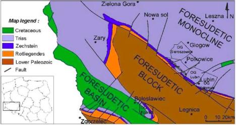
Figure 1. – (a) - 3D model of the Lubin region,
Poland. The thick Zechstein evaporates confine the fluids at the basement and
interface. (b) 2D geological map of the Lubin region and mining district
exploited by KGHM (www.kghm.com).

Figure 2. In-situ recovery scheme
In-Situ
Recovery[3]
ISR is an
environmentally-friendly process by which copper can be extracted from the
ground with minimal disturbance to the surface environment (Figure 2). ISR mining has a long history, starting with
uranium mining in the 1960s.
Advantages to In-Situ Recovery Mining:
- Lower capital and
operating costs
- No waste or ore moved
- No creation of open
holes, waste dumps, leach pads or tailings
- Minimal visual
disturbance
- Minimal noise, dust
and greenhouse gas impact
- Fewer permits are
required compared to other mining processes
- More cost-effective
than most other conventional mining techniques, and thus doesn't require as
many "pounds in the ground" to make the mine economically viable
These advantages allow access to copper
deposits not amenable to conventional mining.
In-situ recovery (ISR) is a non-invasive mining
method whereby boreholes or “injection wells” are drilled into an ore-body,
through which a dilute solution is pumped to dissolve the target minerals or
metals. The solution moves through the rock in a controlled manner to nearby
recovery wells, where it is pumped back to the surface for processing.
Differential pumping rates or natural impermeable barriers are used to control
the movement of the solution through the rock. This, combined with well field
design, prevent any solution from exiting the mine area. For example, an
injection well is usually surrounded by a ring of recovery wells.
The pumping action of the recovery wells make
sure all of the pregnant solution is collected from the injection well. For
example, in ISR mining of copper oxide ores, the dissolving solution is usually
weak sulfuric, the same acid used in open pit and dump or heap leach operations
around the world. In effect, the bore holes or wells become the “mine access”
and the leach pad is “left underground”. Processing is usually done by chemical
precipitation or solvent extraction electro winning (SX-EW).
Building of 3D
reservoir model and hydraulic fracturing application
The following is the representation of creation of the
structural model of small testing area which is in Kupferschiefer deposits in
the Lubin region. The model was constructed with the purpose of performing
hydraulic fracturing on following testing area (Figure 3).
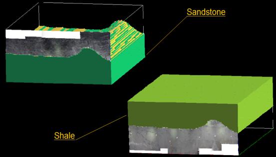
Figure 3. 3D model of testing area
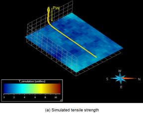
The fracturing process
in gOcad provided by a special wizard developed in the gOcad environment. A
gOcad Wizard has been written by (Cosson and Chaumont, 2013) for simulating
fractures in a medium represented by a Gridded gOcad object. The mechanical
properties of the rock massif are stored in each cell, together with the
induced pressure.
So, after applying the
fracturing has been obtained the results. For better comprehension and to have
a good imagination how the fracturing process affects on permeability, the
fracturing process has been simulated several times with different values of
water initial pressure (Table 3).
Table 1. Initial
injection pressure values
|
Experiment |
Water initial Pressure (inn GPa) |
|
1 |
5 |
|
2 |
10 |
|
3 |
15 |
|
4 |
20 |
|
5 |
25 |
During hydraulic fracturing, when the initial injection
pressure Pinj increases,
as expected the volume of fracked rocks Vf according to a quadratic form passing
through the origin against the initial pressure according to (Figure 4):
|
|
|
(1) |
Discussion:
The fact that the fractured volume Vf reaches a maximum despite that the pressure is
increasing can be related to the Dupuit-Forchheimer radial analytical formula
used to depict the pressure P(r)
variation in the vicinity of the well. As shown in Eq.(1), when the distance r to the well increases, the pressure in
the medium is varying according to P0
/ ln(r). So the resulting pressure might not sufficient to fracture the
medium when the distance is too big. In other words, after a given pressure
sill Pmax which depends on
the nature of the rock, the fractured volume remains quite constant.
Figure
4 illustrates the results of the hydraulic fracturing with the initial
pressures (5; 10; 15; 20; 25; (GPa)), respectively. Figure 4 shows the dependence of
fracked volume on injection pressure.
Figure 4. Dependence of fracked
volume on injection pressure
The maximum fractured volume Vmax depends on the rock type; it seems that more
elastic/ductile rocks such as shale with smaller Young’s modulus E ~ 2.6 GPa,
but with higher tensile strength at T = 2.7GPa the fractured volume is lower
compared to more stiff/elastic rocks such as sandstones with higher Young’s
modulus at E ~ 5.9 GPa with tensile strength at T = 1.8GPa. More experiments
must be carried out to confirm these observations.
As shown in Figure
5, it becomes clear that the
smallest fractured volume corresponds to the lowest pressure value. The volume
of fracked medium increases with the initial pressure; the largest cracked
volume corresponding to the highest initial pressure values. The volumes of
fractured medium against the initial pressure are reported in Table 2.

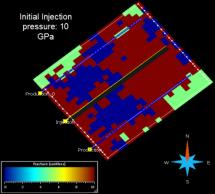
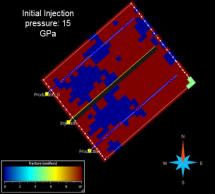

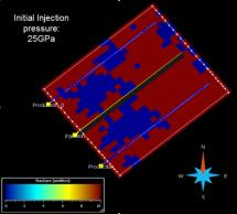
Figure 5. Resulting
fractures induced by stimulation at different values of injection pressure
Table 2. Values of
fracked volume in
accordance with injection pressure
|
Water
initial pressure, GPa |
Volume
of fracked medium, m3 |
|
|
sandstone |
shale |
|
|
5 |
304.2 |
248.4 |
|
10 |
448.0 |
355.0 |
|
15 |
507.0 |
355.0 |
|
20 |
512.2 |
355.0 |
|
25 |
512.4 |
355.0 |
Permeability of
fractures
Before fracturing, the
measured permeability values were about 0.6 mD for sandstone and 0.02 mD for
shale. The above theoretical results show that they can increase to values as
high as from 0.2 to 6 mD assuming an increase factor of 10, and 2 to 60 mD for
an increase factor of 100. Fracturing really increases the permeability of
blocks. To be more precise a flow model should be applied.
Conclusions
This work investigates the way of implementation of ecologically
friendly method which is called In-Situ Recovery in Rudna copper mine site
(Poland). This method is already extensively used in uranium mines of
Kazakhstan, USA, Australia and etc. The main advantages of In-Situ recovery
(ISR) method are: no wastes, no tailings, no underground excavation, no
open-pit and etc.
Considered testing mine Rudna is located in Poland, which is the is the
largest copper ore mine in Europe and one of the largest deep copper ore mines
in the world. As the one of the optimal conditions to use ISR is that the host
rock should be fractured enough to let the solution to flow through it.
Permeability of rocks in Rudna mine is very low to implement the ISR. As the solution
of this problem the artificial way of creating fractures, i.e. hydraulic
fracturing was proposed.
Firstly, the testing site I was modeled in 3D using gOcad, rock
properties being simulated on Sgrid. Fracturing was obtained using a gOcad
wizard and assuming a transverse isotropic medium, elastic properties values
being measured in laboratory. Elastic rock properties were deduced from the
seismic Vp and Vs velocity; the permeability of the rock before fracturing is
very low at 0.7 and 0.02 mD for sandstone ans shale, respectively, increasing
to 60 and 0,2 mD after fracturing. The volume of fractured rock increases with
the injection pressure Pinj according to a quadratic form, like the surface of
the cracked medium
References
1.
Blundell, D.J., Karnkowski, P.H., Alderton, D.H.M.,
Oszczepalski, S., and Kucha, H.(2003). Copper mineralization of the Polish
Kupferschiefer: a proposed basement fault-fracture system of fluid flow.
Economic Geology 98, 1487 - 1495.
2.
Borg G., Piestrzyński, A., Bachmann, G.H., Püttmann
W., Walther S., and Fiedler, M.(2012) - An Overview of the European
Kupferschiefer Deposits. Soc.of Economic Geologists, Inc. Special Pub. 16, 455
- 486.
3.
Carl, T. M., & Michael, B. S. (2010, December). History
of an enduring technology.. (NSI Technologies ) Journal of Petroleum
Technology 2-4 p.
4.
Cosson, C. and Chaumont, A. (2013) - Shale gas and hydraulic fracturing: Wizard manual. ENSG, Nancy,
University of Lorraine, France, Master report M1, 6p.
5.
Gouin, J. (2008) - Mode de genèse et valorisation des
minerais de type black shales: cas du Kupferschiefer (Pologne) et des schistes
noirs de Talvivaara (Finlande). PhD. Thesis Report. Université
d’Orléans.
6.
Hartsch J. (2013) - Copper Mineralisation at the Zechstein
Basis in the North-Sudetic Trough and Geological Model – An Introduction. 23p.
7.
Hudson, J.A., and Harrison, J.P. (1997) - Engineering
Rock Mechanics: an Introduction to the Principles. Pergamon, Oxford, 444 p.
8.
http://www.excelsiormining.com/index.php/in-situ-recovery
9.
Jowett, E.C. (1986) - Genesis of Kupferschiefer Cu-Ag
deposits by convective flow of Rotliegendes brines during Triassic rifting.
Economic Geology 81, 1823 - 1837.
10.
KGHM (2011). Annual Report 2011. http://www.kghm.pl.
11.
Kitterod, N., (2004) - Dupuit-Forchheimer solutions for
radial flow with linearly varying hydraulic conductivity or thickness of
aquifer. Water Resources Research, 40,
1-5.
12.
Mejia, P., Royer, J.J., Fraboulet,
J.G., and Zielińska, A., (2014) - 4D Geomodeling: a Tool for
Exploration – Case of the Kupferschiefer
in the Lubin Region, Poland. Université de Lorraine, CNRS-ENSG,
Vandoeuvre-Lès-Nancy, France. 2KGHM, Cuprum Research &
Development Centre, Wroclaw, Poland, 48p.
13.
Olson, J.E. (2003) - Sublinear scaling of fracture aperture
versus length:An exception or the rule?
Journal of Geophysical Research,
108(B9), 2413-2433.
14.
Oszczepalski, S. (1999) - Origin of the Kupferschiefer
polymetallic mineralization in Poland. Mineralium Deposita 34, 599–613.
15.
Royer, J.J. (2013) - Hydraulic
fracturing in transverse isotropic media. In 33th gOcad Meeting
Proceedings, gOcad Research Group, Nancy, France, 48p.
16.
Royer, J.J. (2012) - Hydraulic
Fracturing in Homogeneous Media. In 33th gOcad Meeting
Proceedings, gOcad Research Group, Nancy, France, 20p.
17.
Robertson, E.P. and Christiansen, R.L. (2006). A Permeability for Coal and Other Fractured,
Sorptive – Elastic Media. Society of Petroleum Engineers, Eastern Regional
Meeting. October 2006. 13 p.
18.
Vaughan, D.J., Sweeney, M.A., Friedrich, G., Diedel, R., and
Haranczyk, C. (1989) - The Kupferschiefer; an overview with an appraisal of the
different types of mineralization. Economic
Geology, 84, 1003 -1027.