BOIKO G.V.
NATIONAL TECHNICAL UNIVERSITY OF UKRAINE
"IGOR SIKORSKY KYIV POLYTECHNIC INSTITUTE"
THE MOTION OF THE HULL OF THE HYPERSONIC AIRCRAFT AT
AN ANGLE
We will analyze the side surface of the float gimbal and and
its resilient co-operating with acoustic radiation penetrating
from outside.
A sound-wave unavoidable results in the resilient
moving of the surface in radial ![]() and
tangential
and
tangential ![]() directions (relative motion),
that in the conditions of the
portable angular motion of the aircraft fuselage with velocity
directions (relative motion),
that in the conditions of the
portable angular motion of the aircraft fuselage with velocity ![]() will be responsible Euler forces (forces of Coriolis inertia, and more precisely, moments of inertia forces ) and, naturally, inciting moments
will be responsible Euler forces (forces of Coriolis inertia, and more precisely, moments of inertia forces ) and, naturally, inciting moments ![]() and
and ![]() (Fig. 1).
(Fig. 1).
Constituents ![]() and
and ![]() of these moments will result in precession of the main axis and, accordingly, the error of measuring will appear :
of these moments will result in precession of the main axis and, accordingly, the error of measuring will appear :
 ;
; ![]() ;
; ,(1)
,(1)
where
![]() - is a moment of inertia of the float,
- is a moment of inertia of the float, ![]() - is the
angular momentum of the gyroscope.
- is the
angular momentum of the gyroscope.
Now will find out the
degree of influence of the forced bend moving ![]() of the surface of head ends of the float. The presence
of relative and portable motions, as in the previous case, will
result in inciting moment of Coriolis inertia forces of
of the surface of head ends of the float. The presence
of relative and portable motions, as in the previous case, will
result in inciting moment of Coriolis inertia forces of ![]() (Fig. 2)
(Fig. 2)
![]() .
(2)
.
(2)
In accordance with the Resal theorem this moment will form the instrumental errors
 . (3)
. (3)
Thus, the integral error of the gyroscope will equal:
![]()
![]() .
(4)
.
(4)
Will analyse the inciting motion of the float in flight. We will hard
bind the system of co-ordinates ![]() with
the body of aircraft:
with
the body of aircraft:![]() will be sent along the axis of the aircraft,
will be sent along the axis of the aircraft, ![]() and
and ![]() will be placed in the former plane. For the supporting system of
co-ordinates we
will choose the
axes which are related to Earth. Axis
will be placed in the former plane. For the supporting system of
co-ordinates we
will choose the
axes which are related to Earth. Axis ![]() will be sent vertically downward, axis
will be sent vertically downward, axis ![]() - horizontally (for example, directed on the line of the set course), axis
- horizontally (for example, directed on the line of the set course), axis ![]() constitutes the right three of axes
constitutes the right three of axes![]() with the first two axes.
with the first two axes.
Let the aircraft at
the moment of start occupies
a free position. Let’s draw a plane through its mass
center, perpendicular to the longitudinal axis (the former plane) to the
crossing with the horizontal plane ![]() . For the crossing lines of these planes
. For the crossing lines of these planes ![]() (lines of
knots) we will direct axis
(lines of
knots) we will direct axis ![]() and will draw
in the horizontal plane axis
and will draw
in the horizontal plane axis![]() , perpendicular
to
, perpendicular
to ![]() . For the Euler angles we will
choose the angle of turning
round the vertical
line of the horizontal co-ordinate plane
. For the Euler angles we will
choose the angle of turning
round the vertical
line of the horizontal co-ordinate plane ![]() to its
coinciding with the axes of the system
to its
coinciding with the axes of the system ![]() (let’s call it the angle of
yaw
(let’s call it the angle of
yaw ![]() ), the angle
of turning round the line of knots
), the angle
of turning round the line of knots ![]()
![]() of the
co-ordinate plane to coinciding of axis
of the
co-ordinate plane to coinciding of axis ![]() with the
longitudinal axis of the airplane. We will call
with the
longitudinal axis of the airplane. We will call![]() -
the angle of pitch (in this case axis
-
the angle of pitch (in this case axis ![]() will occupy the
position of
will occupy the
position of ![]() in the former’s plane) and the angle
of turning of
the plane
in the former’s plane) and the angle
of turning of
the plane ![]() about the
longitudinal axis of the fuselage
about the
longitudinal axis of the fuselage ![]() (angle of roll
(angle of roll ![]() ). The
corresponding angle rate
will be directed along the vertical line
). The
corresponding angle rate
will be directed along the vertical line ![]() ,
the line of knots
,
the line of knots ![]() and along the
axis of the vehicle
and along the
axis of the vehicle ![]() .
.
The angle rate of the
aircraft can be shown as hands for the unitary vector ![]() of axes
of axes ![]() ,
, ![]() and
and ![]()
![]() ,
(5)
,
(5)
or in projections on the
axes which are connected to the body of
the vehicle -
![]() . (6)
. (6)
When
the aircraft starts from an immobile base (the axes ![]() are immovable),
the projections of angle
rate on axis
are immovable),
the projections of angle
rate on axis ![]() , which are connected with the fuselage, are calculated by the
formulas (fig. 3, fig. 4) :
, which are connected with the fuselage, are calculated by the
formulas (fig. 3, fig. 4) :
![]() ;
; ![]() ;
;
![]() ;
; ![]() ; (7)
; (7)
![]() ;
; ![]() ,
,
where ![]() ;
; ![]() ;
; ![]() .
.
Conversely,
when the start is carried out from a
mobile base (for example, a carrier-aircraft),
at first it is necessary to resolve angle
rate into the axes![]() . It also conserns the case, when it
is necessary to take into account the angle rate of
day's rotation of Earth.
. It also conserns the case, when it
is necessary to take into account the angle rate of
day's rotation of Earth.
Assume that the angles ![]() and
and ![]() , and also their derivatives in time,
small. The angle rate of yaw we
will show as -
, and also their derivatives in time,
small. The angle rate of yaw we
will show as -
![]() , (8)
, (8)
where ![]() - the
size which is measured by the
angle rate sensor, for
example, at the aircraft
rotation, and
- the
size which is measured by the
angle rate sensor, for
example, at the aircraft
rotation, and ![]() <<
<<![]() is rather small
indignation of this angulator.
is rather small
indignation of this angulator.
Obviously, that constituents ![]() and
and
![]() do not carry out the
influence on the error of gyroscope,
because they coincide after direction from the
figure. At the same time, kinematic inciting
do not carry out the
influence on the error of gyroscope,
because they coincide after direction from the
figure. At the same time, kinematic inciting ![]() and
and ![]() will result in the additional error of measuring (Fig. 4)[1]:
will result in the additional error of measuring (Fig. 4)[1]:
![]()
![]()
![]() .
(9)
.
(9)
The
angle rate vector ![]() and angular
acceleration
and angular
acceleration ![]() are directed
along the initial axis of the
unit.
are directed
along the initial axis of the
unit.
The
analysis proves that the angle
rate ![]() of the fuselage during
the acoustic vibration of the
float butt ends results in a
spiral motion, that, itself, is a necessary factor, because it reduces
dry friction on the float
axis. But together
with the resilient radial motion
of the fuselage during
the acoustic vibration of the
float butt ends results in a
spiral motion, that, itself, is a necessary factor, because it reduces
dry friction on the float
axis. But together
with the resilient radial motion ![]() of the side surface
of the float, the
angle rate
of the side surface
of the float, the
angle rate ![]() will start the
appearance of the moment of Euler forces (forces of Coriolis inertia) and, naturally, will result in the origin of
angle rate
will start the
appearance of the moment of Euler forces (forces of Coriolis inertia) and, naturally, will result in the origin of
angle rate ![]() , directed
parallel to the ingoing axis, the
axis of sensitivity, and the device
(Fig. 5), :
, directed
parallel to the ingoing axis, the
axis of sensitivity, and the device
(Fig. 5), :
![]() . (10)
. (10)
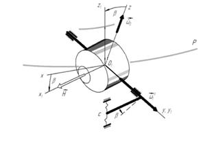
Fig. 4. Origin of angular
acceleration Fig. 5. Origin joint action to gyroscope
![]() kinematic and acoustic action
kinematic and acoustic action
The tangential resilient displacements ![]() of the side surface,
at the given angle
rate
of the side surface,
at the given angle
rate ![]() , lead
to appearance of forces of Coriolis inertia, which
lines of action will
cross the center of the
gimbal and will not create the inciting moment.
, lead
to appearance of forces of Coriolis inertia, which
lines of action will
cross the center of the
gimbal and will not create the inciting moment.
Thus, the
aircraft angular motion with
velocities ![]() and
and ![]() serves to negative influence of acoustic
vibration on the device as a factor
serves to negative influence of acoustic
vibration on the device as a factor ![]() on the outgoing axis. In its
turn, the angle rate
on the outgoing axis. In its
turn, the angle rate ![]() of the fuselage will
underline the radial resilient movements of the
side surface of the
float
of the fuselage will
underline the radial resilient movements of the
side surface of the
float ![]() , imitating
the presence of "erroneous"
input value of the
device
, imitating
the presence of "erroneous"
input value of the
device ![]() .
.
References
1. Mel'nik, V.N.
Stress-strain state of a gyroscope suspension under acoustic loading [Текст]/
V.N. Mel’nik // 2007; Strength of
Materials. ISSN: 00392316. Volume: 39. Issue: 1. Pages: 24-36. Year:
2007-01-01. EID: 2-s2.0-34147198666. Scopus ID: 34147198666. DOI:
10.1007/s11223-007-0004-6.