Smolentsev V.P. (Doctor of Technical Science), Safonov
S.V. (Candidate of Pedagogical Science), Koptev I.I.
Voronezh State Technical University
The
improvement of the flow duct of heat engine sprayers
The article deals with issues related to customizing the flow duct of
heat engine sprayers. It discovers the scope of effective implementation of
electrical processing methods, the use of which has not only enabled the
successful modification of the duct
area, but has also helped to impart the nozzle shape to the duct. This task is
not feasible with other processing methods due to limited tool access to the
nozzle at the supply end of the flow duct. The problem of component spray
management has been solved for sprayers working together on a single fire board.
Кew words: sprayer, flow duct, channels, consumption,
spraying, channel shape, electrical processing methods.
Introduction
In the manufacture of heat
engines, it is required to apply different types of sprayers supplying the fuel
to the combustion zone, while ensuring the individual conditions for media
flowing in each channel. The main criteria of evaluating the performance of
sprayers are the consumption of components and the jet spray at the outlet of
the channel. Both figures must be within the range, established for each
channel. If sprayers are combined as one fire wall, board or base, it is
necessary to obtain the individual characteristics of them depending on their
location on the fire wall, and ensure the required jet interaction in the
process fluid during its supply to the combustion zone, using technological
methods. The configuration of sprayers, based merely on component consumption,
does not allow to obtain the required operational parameters since it does not
provide the desired combination of total jet density and total consumption of
air-fuel mixture. Testing the multijet sprayers may reveal the section size of
one or several channels exceeding the limit values, specified by the drawing.
Previously, such products were considered to be faulty, which could entail
heavy material loss and the failure to meet the deadline for assembly of
newly-made product sets.
The new techniques and devices proposed by the authors as inventions,
are used for implementing the combined methods of creating channels in sprayers
while inducing an electrical field, which permits to shape the high-quality
channels of any profile (including the ones with a Laval nozzle profile),
having an adjustable section and ensuring the desired spraying. These
techniques provide greater opportunities for developers in designing heat
engines for new-generation aircrafts, and improve the world market position of
manufacturers, creating the faultless popular high-quality science-based
products for supplying the combustible media.
The rationale for selecting the solution of the posed
tasks
The developed new techniques and devices [1,2] have
shown that the application of combined processing methods with inducing an
electrical field allows to shape the flow channel of sprayers not only by
increasing the area of flow sections, but also by reducing this parameter
through growing the high-grade layer in small-sized holes. This provides the
required stability of air-fuel mixture consumption within a single multijet
sprayer and during the combined work of several sprayer types, located on a
single firewall.
The solution to the problem of shaping the flow duct
of sprayers with a variable section and profile was made possible through the
contact-mechanical method, by adjusting the electrical field energy in process
of cathode coating deposition, or by local anodic dissolution of the
small-section channel material. It proved advisable [3,4,5] to adjust the spray
coverage by using the dimensional processing, which is performed by altering
the edge geometry at the jet inlet/outlet, due to individual shaping of
transitional channel zones in separate sprayers and their combinations located
on a single firewall. The variation in removal and deposition of material,
occurring during combined processing, has been attained by regulating the
amount of electricity with regards to processing time for each channel, and
also by reasonable setting of fixed and variable speed of zone processing for
small-section channels.
The new technological equipment [6,7] has been developed for
implementing the proposed methods of electrical processing. It is shown that
the performance of the technological operations for improving the flow duct of
engines is possible with using modern equipment and means of automatization (including
the imported ones), purchased by Russian enterprises.
The new
methods and devices for regulating the flowing of the operating media in
sprayers
In the manufacture of sprayers (especially, the multijet ones), working
together on a single fire board, it is necessary to ensure the required
consumption of air-fuel mixture and the appropriate angle of spraying.
The consumption is largely determined by the flow section area of the
channel supplying the air-fuel mixture to the combustion zone. For this purpose
it is required to either increase or reduce the diameter of one or several
holes. As a rule, the expansion of flow sections is carried out by
electrochemical processing using the profile metal tool in small-section
channels, given the limited ability of an electrode to pass through the
transitional “trunk channel” section. To implement this method, it has been
proposed to apply the tensile force of not more than half the yield strength to
a thin wire serving as an electrode, in order to prevent short circuits between
the electrodes [4,5].
The previously known processing methods do not allow to reduce the area
of the channel for supplying the air-fuel mixture. The article proposes the
method and tooling for producing high-quality coating (of tenths of a
millimeter thick) in deep holes. For this purpose, the chromium-plating
technique [5,6] is used, which is developed by Voronezh scientists and
performed with a special tool, shown in fig. 1.
Fig. 1. The tool for nanocoating deposition in
small-section holes (as exemplified by a sprayer)
1
– sprayer hole; 2 – tool electrode
(conducting wire); 3 – burnishing belts; 4 – operating medium (electrolyte); 5
- coating; Р – the force of tool movement in the hole
The developed mechanism of controlled coating deposition on the side
surface of small-section channels made it possible to justify the speed of
electrode movement along the hole, and create the methodology of calculating
the technological modes and tool parameters for combined galvano-mechanical processing.
The most complicated task is to control the spray of burning gas-liquid
combustible mixture with variable, poorly regulated parameters and at high
differential pressure, modifying the gas filling pattern and other jet
parameters in the sprayer channel [8,9]. The eddy flows observed at the nozzle
section can be altered by creating the transitional zone at the rounded nozzle
channel section.
The conducted research has shown that, in the case of small jet
cross-sections, the pulsing flow must conform to regularities according to
which the pulsating motion of multiphase medium is characterized by the
emergence of single or double vortex.
The numerical calculation methods (with significant tolerance) allow to
create the pattern of vortex, generated by compression shock at the nozzle
section, and provide a qualitative description of air-fuel mixture movement
along the edges of the spray cone. It
is shown, that vortex parameters depend on the edge rounding radius which can
only be found by controlled electrochemical dimensional processing.
The fig. 2 presents the scheme of transitional zone
formation by radii the value of which depends upon processing time.
Fig. 2. The scheme of edge rounding radius formation
at the section of a sprayer
а) – general view; b) – the dynamics of radius
formation (/, II, III);
1 – sprayer hole; 2 – tool electrode; r1 ,r2 , -
rounding radii, S0 – the initial interelectrode gap
The mechanism for managing the process of preset radius formation may be
implemented under the following assumptions:
·
The removal of metal from the edge has a local character, which
allows to assume that the resulting edge rounding radius closely corresponds to
the circular segment.
·
The current, supplied for anodic dissolution, is concentrated on
the edge during the whole period of processing. The more rigorous description of anodic dissolution assumes not only
the current concentration on the edge, but also its dissipation over the outer
surface of a sprayer, close to the hole. In this case, the quantitative
indicator of current density will be variable, depending on the edge rounding
radius value (r1 > r2
as shown in fig.2). However, this assumption is quite reasonable, in view of
small change in the radius, typical for conditions of sprayer
customization.
·
The removal of metal from the edge is performed along the bisected
line of the angle.
The initial conditions are as follows:
·
The processing is performed in accordance with the scheme
comprising fixed electrodes;
·
The same interelectrode gap (S0 as shown in fig. 2) is set for all edges during their
customization;
The requirements are known, which specify the value of
the edge rounding radius, set experimentally depending on spraying necessary
for each channel.
The boundary conditions are as follows:
·
The variation of the edge rounding radius is within narrow limits
and does not exceed 0.1 mm for edges of small-section holes.
·
The edge rounding radius has
the same value along the edge length (within tolerance) ;
In this case, the control
parameter of edge rounding radius formation (r) will be the processing time,
defined by the formula (1)
![]() (1)
(1)
where ![]() is the density
of the material processed,
is the density
of the material processed,
![]() is current
output
is current
output
![]() is the
electrochemical equivalent of the material processed
is the
electrochemical equivalent of the material processed
![]() is the
conductivity of the process medium
is the
conductivity of the process medium
![]() is the
electrode voltage
is the
electrode voltage
![]() is the loss of
electrode voltage in the interelectrode gap
is the loss of
electrode voltage in the interelectrode gap
The speed of electrolyte pumping
through the gap must be not less than
 (2)
(2)
In this case, ![]() is kinematic
viscosity,
is kinematic
viscosity,
![]() is the density
of treatment products (not more than 2.5∙10-3 g/mm3)
is the density
of treatment products (not more than 2.5∙10-3 g/mm3)
![]() is the concentration of treatment products on the edge
(Cα = 0.95 – 0.97)
is the concentration of treatment products on the edge
(Cα = 0.95 – 0.97)
![]() is the concentration of treatment products at the
inlet (Cвх = 0.04 – 0.05)
is the concentration of treatment products at the
inlet (Cвх = 0.04 – 0.05)
![]() is the
coefficient of treatment product diffusion in the flow
is the
coefficient of treatment product diffusion in the flow
![]() = 0.96 ∙
10-3 [1+0.03 (T −273)], (3)
= 0.96 ∙
10-3 [1+0.03 (T −273)], (3)
where T is the average
temperature of electrolyte.
The electrolyte pressure (P)
in the vicinity of the edge must ensure the flow speed, calculated using (2).
With certain tolerance, the value P can be derived from the following
dependence:
![]() (4)
(4)
where
![]() – is the dynamic viscosity of
the medium
– is the dynamic viscosity of
the medium
The
time necessary for obtaining the required edge rounding radius closely
corresponds to experimental results (fig.3), since the radius tolerance is up
to 1/3 of its nominal value.
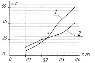
Fig.3
The processing time, required for rounding the edge by the radius ![]()
![]() = 0,1 mm,
= 0,1 mm, ![]() = 5,3 m/s, the workpiece
material is copper alloy, the electrode voltage is 9 V.
= 5,3 m/s, the workpiece
material is copper alloy, the electrode voltage is 9 V.
1
– the calculated dependence, 2 – the experimental dependence
Conclusion
On the basis of patented methods and
devices, the technology has been developed for customizing the channels by
combined methods with inducing an electrical field in various types and
combinations of sprayers, used for supplying gas-liquid mixture, which allowed
to implement the promising projects of heat engines in conditions of mass
production. The techniques and devices have been created combining the
regulated force actions and adjustable electric fields within a single
technological process for obtaining high-reliability coatings in channels of
various sections (with an area of less than 1mm2) that was
previously unattainable. The mechanism has been developed to create the local
channel zones (also involving the formation of a Laval nozzle profile) with a
section area of less than 1mm2, and the system of controlling the
technological modes of combined processing, in consideration of feedback on
process parameters. This has made it possible to design the technologies of
combined processing and calibration of critical components in the flow section
of single- and multijet sprayers, working individually or as part of fire
boards (walls, bottoms), having sprayers of several typical sizes.
References
1.
Patent № 2303087 Russian Federation, IPC7.The
method and device for local electrochemical processing of channel edges
(Authored by V.G.Gritsyuk, V.P.Smolentsev, I.T.Koptev et al.) "The
Bulletin of Inventions". № 20, 2007.
2. Patent № 2333821 Russian
Federation, IPC7.The method of electrochemical dimensional
processing and the device for its implementation (Authored by V.P.Smolentsev et
al.) "The Bulletin of Inventions" № 26, 2008.
3. Patent № 2470749 Russian Federation, IPC7. The method of
electrochemical processing of local zones and the device for its implementation
(Authored by I.T.Koptev, V.P.Smolentsev et al.). "The Bulletin of
Inventions" № 2 36, 2012.
4.
Norman A.V. The analysis of methods, used
for customization of small-section channels
// The non-conventional methods of processing: the collection of
scientific works. Moscow: Маshinostroenie,
2006. Issue. 8, 4.1- PP. 218 - 224.
5. Norman A.V. The adjustment of the diameter size of small-section holes
by coating deposition // The Production of Special Equipment: the
inter-university collection of scientific works. Voronezh: VSTU, 2004. - PP. 50
- 54.
6.Chizhov M.I.
Galvano-mechanical chroming of machine components [Теxt] / M. I. Chizhov, V.P.Smolentsev // Voronezh: VSTU,
1998. -162 p.
7.
Norman A.V. The equipment for producing the small
diameter holes // The non-conventional methods of processing: the
inter-university collection of scientific works; Voronezh, VSTU, 2005. Issue 7.
– PP.119 - 125.
8.Коptev I.I. The production and configuration of sprayers for supplying the
combustible mixtures / I.I.Koptev, V.P.Smolentsev, E.A.Saltanaeva // The
assembly in instrument-making and machine construction. - 2013. - №1 - PP. 3-7
9. Коptev I.I. The control of manufacture and customization
of sprayers // A student. A specialist. A professional. - 2013: The proceedings
of the VI international academic and practical conference. - Voronezh: The
Centre of Scientific and Technical Information, 2013. - PP. 182-183.
Credits:
Smolentsev Vladislav Pavlovich – Doctor of Technical Science, Professor, Voronezh State Technical University. Business
address: VSTU, 14, Moskovsky Prospekt, Voronezh, 394026 Тel.9036559970. E-Mail: vsmolenHYPERLINK
"mailto:vsmolen@inbox.ru"@inbox.ru
Smolentsev Vladislav Pavlovich – Doctor of Technical Science, Professor, Voronezh State Technical University. Business
address: VSTU, 14, Moskovsky Prospekt, Voronezh, 394026 Тel.9036559970. E-Mail: vsmolen@inbox.ru
Safonov Sergey Vladimirovich –
Candidate of Pedagogical Science, Professor, Voronezh State Technical
University. Business address: VSTU, 14, Moskovsky Prospekt, Voronezh, 394026
Коptev Ivan Ivanovich, postgraduate, Voronezh State Technical University.
Business address: VSTU, 14, Moskovsky
Prospekt, Voronezh, 394026