Ekaterina Lozovskaya, Sergey Balabaev, Konstantin
Rumyantsev
Southern Federal University
105/42 Bolshaya Sadovaya Str., Rostov-on-Don, 344006, Russia
The mathematical model of the recording video camera for the height
measurement of the regularly situated objects.
The
priority direction in the в
domain of noncontact measuring of geometric object’s parameters is the creation
of the telemetric control systems, admitting to find the image of the measuring
objects using the video camera and to make their analysis by the digital signal
processing methods on the personal computer base [1].
One of
the fundamental directions in the atomic energetic is the creation of the
high-reliability informational managing complexes, as far as the use of the
superannuated manage systems of the
technological process vastly reduce the effectiveness of the nuclear power
plant(NPP). [2].
The index having an influence on the safety of the realizing dangerous nuclear labors is the
height of the fuel assemblies’ heads (FA),characterizing
their curvature, which for certain values makes it impossible to
operate the reactor core [3-4]. The main performance criterion of the height’s
control of the heads FA is to minimize the measurement error.
Improving noncontact (visual) method
for determining the height of the nuclear reactor’s heads FA on the basis
of three-dimensional image reconstruction is necessary to improve the accuracy
of measurements.
Known noncontact (visual) method [5]
of the definition the height of the nuclear reactor’s heads FA based on the
reconstruction of three-dimensional images. The method is of the height’s
control based on a series of the consistently produced images of one camera
from different angles, which are then transmitted to a computer for processing.
Method [5] provides for a stereo pair of images in the system at the
exact setting (moving) a video camera to the given point of the space.
In a typical three-dimensional image space the distance information to
the elements of the scene appears only in the form of indirect evidence: in the
relative sizes of the objects, shading some objects by others, different
illumination, etc. One way to obtain information about the height’s objects is
the registering multiple images at different angles scene. In this case, the
points of the scene give the images, the relative position of which depends on
the distance to the observation point. Comparing these images there is
possibility to reconstruct the three-dimensional structure of a scene using a
technique [1, 6].
Feature measurement
the height’s heads FA is to use one camera, and the video camera subsequent
fixation in certain points of space is provided for the creating stereo system.
At that the three-dimensional reconstruction of the scene takes place on two
images from different angles.
Two cameras located
at different points, record the same scene, but the optical axes of the video
cameras are not parallel and the direction of displacement of the optical
center of the one video camera relative to another video camera’s optical
center arbitrarily (Fig.1).
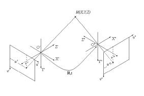
Fig. 1. The system
of two arbitrarily oriented video cameras
The
purpose of research is to develop a mathematical model of the recording video
camera, which will assess the method error of the measurement of geometrical
parameters due to the imperfection of the measurement method and the
simplifications made by indirect measurements [7-8].
The
proposed model of the imaging enables to establish communication between the
points’ coordinates of the scene and their images, to determine the parameters
of the registration’s system and the three-dimensional structure of the scene
of the group FA [5]. Nuclear reactor fuel assembly can be seen visually as a
"cell" of seven cylinders , and six of them are located at the
vertices of a regular hexagon (positions (1)-(6) in Fig. 2) , and the seventh
is at its geometric center (position (0) in Fig. 2) . The investigate objects
are the regular structure and situated in an aqueous medium in a strictly
defined order. The object’s rods in Fig. 2 are conditionally designated the
points. R is radius of the cell FA.
Fig. 2. Object in
the form of a regular hexagon
In the developed MathCAD model the video camera is CDR
3223 Baxall with lens focal length f = 2, 84 mm, matrix size 1/2 ", and a
definition of 752x582.
The optical center of the video camera is located on a
circle with a radius of rotation D / 2, the center O of which is the rod’s axis
(Fig. 3). It is assumed that the rod’s axis is perpendicular to the plane of
the hexagon at its geometric center (position (0)).
Fig. 3. The video camera fastening
The
height of suspension of the video camera over the “cell” is H and is determined
basing on the coverage of all seven rods field of video camera’s vision. In
this case the optical axis of the video camera also passes through the rod (0)
(Fig. 3).
The
three-dimensional coordinates of the points are specified in the global
coordinate system (GCS), not coinciding with the standard coordinate system of
video camera (SCS) (Table 1).
TABLE I
Coordinates of rods’ points in gcs
|
|
x |
y |
z |
|
p.0 |
0 |
0 |
0 |
|
p.1 |
-0.5 |
0 |
-0.866 |
|
p.2 |
0.5 |
0 |
-0.866 |
|
p.3 |
1 |
0 |
0 |
|
p.4 |
0.5 |
0 |
0.866 |
|
p.5 |
-0.5 |
0 |
0.866 |
|
p.6 |
-1 |
0 |
0 |
Transition
from GCS to SCS is done by turning the coordinate axes system SCS and
subsequent displacement of the origin by a distance L (Table 2).
TABLE II
Coordinates rods’ points in scs
|
|
x |
y |
z |
|
p.0 |
0 |
0 |
2.236 |
|
p.1 |
0.5 |
0.387 |
3.011 |
|
p.2 |
-0.5 |
0.387 |
3.011 |
|
p.3 |
-1 |
0 |
2.236 |
|
p.4 |
-0.5 |
-0.387 |
1.461 |
|
p.5 |
0.5 |
-0.387 |
1.461 |
|
p.6 |
1 |
0 |
2.236 |
In the
standard system, the projections of the three-dimensional points coordinates
are the coordinates in the video camera image (Table 3).
TABLE III
Coordinates of the rods’ points in the image plane of video camera
|
|
x |
y |
|
p.0 |
0,00 |
0,00 |
|
p.1 |
0.472 |
0.365 |
|
p.2 |
-0.472 |
0.365 |
|
p.3 |
-1.27 |
0,00 |
|
p.4 |
-0.972 |
-0.752 |
|
p.5 |
0.972 |
-0.752 |
|
p.6 |
1.27 |
0,00 |
For a
complete description of the video camera is necessary to evaluate the
coordinates of points in the image plane in the natural units of the photo
detector (Table 4).
TABLE IV
Coordinates of the rods’ points in the natural units of the photo detector
(pics)
|
|
x |
y |
|
p.0 |
0,00 |
0,00 |
|
p.1 |
57.182 |
42.89 |
|
p.2 |
-57.182 |
42.89 |
|
p.3 |
-154.003 |
0,00 |
|
p.4 |
-117.847 |
-88.393 |
|
p.5 |
117.847 |
-88.393 |
|
p.6 |
154.003 |
0,00 |
At the
same time a mathematical model allow to
determine the number of pixels, in which each point is (Table 5.6). If the
coordinates do not fall within the photosensitive matrix, the program assigns a
value of zero pixel.
TABLE V
Pixel number of the hexagon points in the system of vc1
|
VC1 |
x |
y |
|
p.0 |
0 |
0 |
|
p.1 |
58 |
43 |
|
p.2 |
-58 |
43 |
|
p.3 |
-154 |
-1 |
|
p.4 |
-118 |
-89 |
|
p.5 |
118 |
-89 |
|
p.6 |
154 |
1 |
TABLE VI
Pixel number of the hexagon points in the system of vc2
|
VC2 |
x |
y |
|
p.0 |
0 |
0 |
|
p.1 |
154 |
1 |
|
p.2 |
58 |
43 |
|
p.3 |
-58 |
43 |
|
p.4 |
-154 |
-1 |
|
p.5 |
-118 |
-89 |
|
p.6 |
118 |
-89 |
The
create of two video camera stereo
system, oriented at an angle of 60 ° (Fig. 4), enables to evaluate the
three-dimensional coordinates of the points of the hexagon in the coordinate
system of any of the cameras.
Fig. 4. Regular hexagon with the planned position of
video camera
At the
same time, having the coordinates of points in the natural photo detector units
in the coordinate system of video camera (VC) 1 (the first camera position) and
video camera (VC) 2 (the second camera position), there is possibility to
calculate the vectors of three-dimensional coordinates of points in the systems
VC1 and VC2 (Table 7, 8).
TABLE VII
Coordinates of the rods’ points in scs1
|
VC1 |
x |
y |
z |
|
p.0 |
0 |
0 |
2.236 |
|
p.1 |
-0.719 |
0.55 |
-4.27*10^-3 |
|
p.2 |
-1.287 |
-0.985 |
7.643*10^-3 |
|
p.3 |
-1.585 |
0.011 |
3.545*10^-3 |
|
p.4 |
-0.712 |
0.554 |
2.079*10^-3 |
|
p.5 |
-1.293 |
-1.006 |
-3.772*10^-3 |
|
p.6 |
-1.576 |
0.011 |
-3.523*10^-3 |
TABLEVIII
Coordinates of the rods’ points in scs2
|
VC2 |
x |
y |
z |
|
p.0 |
0 |
0 |
2.236 |
|
p.1 |
1.573 |
-0.011 |
3.518*10^-3 |
|
p.2 |
1.303 |
-0.997 |
7.738*10^-3 |
|
p.3 |
0.719 |
0.55 |
-4.27*10^-3 |
|
p.4 |
1.574 |
-0.011 |
-3.519*10^-3 |
|
p.5 |
1.285 |
-1 |
-3.75*10^-3 |
|
p.6 |
0.723 |
0.563 |
2.11*10^-3 |
For the
evaluation of three-dimensional coordinates of points on a stereo pair is
necessary to know the internal parameters of video cameras (the calibration
task) and to know the parameters of the mutual arrangement of video cameras
(the problem of relative orientation). After solving these problems in the
images the coordinates of the corresponding data points conjugate points can be
found (the task of finding conjugate points).
Thus,
during the research, a mathematical model of the object, enabling to determine
the coordinates of the points of the hexagon in the global coordinate system
(GCS). There are determined the correlations for the conversion of coordinates
from GCS in SCS with the following displacement of the origin; calculated the
coordinates in natural units photo detector; reconstructed the
three-dimensional coordinates of objects on the basis of SCS coordinates of
their projections in the images of a stereo pair, made a reverse
conversion of coordinates from GCS to SCS .
The
proposed mathematical model enabled to recalculate the coordinates of the
points of the GCS to SCS and the inverse. The relations will assess method
error of measurement of geometrical parameters due to the imperfections of
contactless measurement method or simplifications made during
measurements by reconstructing the three-dimensional scene on a series of
images.
Acknowledgment
We wish to thank the
Department of information security for their insightful comments on earlier
drafts.
References
[1] Methods of computer
imaging / edited by V.A. Soifer - M. :
Fizmatlit, 2001. - 784 p.
[2] Balabaev S.L., Radetzky V.G.,
Rumyantsev K.E. Telemetry control method of the height of the cylindrical
objects. Southern Federal University. Engineering. 2008. T. 80. Number 3. Pp.
94-110.
[3] Balabaev S.L., Radetzky V.G.,
Rumyantsev K.E. Video System contactless control of the height of objects.
Southern Federal University. Engineering in 2006. T. 64. № 9-1. Pp. 157-161.
[4] Korobkin V.V., Korovin Y.S.,
Khisamutdinov M.V., Rumyantsev K.E., Balabaev S.L., Makeev V.V. Contact
detection system of the height of the heads nuclear reactor fuel assemblies
(FA). A utility model patent RUS 103963 22.12.2010.
[5] I.A. Kalyaev, K.E.
Rumyantsev, V.V. Makeev , S.L. Balabaev , V.V. Korobkin , J.S. Korovin , A.P.
Kuharenko , V.G. Radetzky. Non-contact method for determining of the height of
the heads nuclear reactor fuel assemblies on the basis of three-dimensional
reconstruction images /Southern Federal University. Engineering. 2008. T. 80.
Number 3, p.126 -131.
[6] Gruzman I.S., Kirichuk
V.S., Kosyh V.P., Peretyagin G.I., Spector A.A. Manual. Digital image
processing in information systems. Novosibirsk: Publishing House of the NGTU,
2002. - 352.
[7] Rumyantsev K.E., Balabaev
S.L., Zibrov V.A Non-contact measurement of geometrical sizes of rolled
products and steel industry. Shakhty: Publisher URGUES, 2004 - 156 p.
[8] M.L. Lopatin, S.L.
Balabaev. The complex reconstruction of three-dimensional models of objects /
News of higher educational institutions. North Caucasus region. Engineering. -
2011. - With. 9-12.