Elizabeth S. Gusyentsova, Inna K. Nasonkina, Yana A.
Gusyentsova, Konstantin N. Andriychuk
East Ukrainian National University named after
Vladimir Dahl
ANTISTALL
DEVICES FOR AXIAL FANS
The questions of
stability of fan’s operations modes belong to the number of most difficult and
insufficiently known. It is caused by complication of solution hydrodynamics equations
and determination of one or another turbulence hypothesis. In addition, work on
unstable modes causes growth of dynamic tensions in the elements of
construction and often results the fan’s fail [1-4].
It is possible to
consider grid and rotating stall the most studied forms of unstable
fan’s operation. However there is no admitted theory yet, which would most
fully describe these phenomena. There is little quantity of devices, which can
fail-safely remove harmful influence of these phenomena on axial turbo-machine
work.
The surge origin
depends not only on the fan’s operations mode but also on network features. Therefore
it is impossible to talk about a point on pressure characteristics of fan, in
which the surge appears. This point can shift depending on parameters of joint to
fan network. Transition of fan to the mode of rotating stall takes place at certain
mode on pressure characteristics and does not depend on the network capacity.
It is determined by structural and geometrical sizes of flowing part and machine
blade row. At transition on the rotating stall mode (on the left-hand from pressure
maximum) the pressure developed by fan decreases abrupt, the characteristics
discontinuity appears and typical noise change occurs, created at machine work.
It is determined
that surge occurs at machine work in area of rotating stall, at the discontinuity
of pressure characteristics and rather big reverse inclination of pressure characteristic
on the left-hand from pressure maximum.
Obviously, for solution
the question about extension of steady fan work area, above all things, it is
necessary to prevent possibility of appearance of rotating stall mode or separate
the stall area from basic stream part.
It is possible to
consider decreasing the aerodynamic loadings of workings grid of fan the
simplest solution of the question of unsteady modes of work elimination. Thus
pressure characteristics have monotonic falling view without maximums and minimums
of pressure. Usually it is achieved at the small blade angles setting of fan impeller (less than 10 - 15°).
In this case neither rotating stall nor surge do not occur in whole productivity
diapason from maximum to zero. However decrease of aerodynamic loadings of
workings grid conduces increase of sizes and rise in prices of machine that in majority
of cases does not prove its value. For
such grids appearance of the modes with rotating stall and surge is inevitable,
if special measures are not foreseen.
It is shown [4], that vane separators with the number of vanes of z ~
200 effectively work at the comparatively low aerodynamic loadings on one
stage, with angle of rotor vane setting no more then 35°, at the developing
coefficient of pressure 0,18—0,2. Efficiency
factor decreases on 1—2%. Sharply expressed frequency constituents appear, conditioning
high audio-frequency fan noise, because of big number of separator vanes in
noise spectrum. For fans with meridian acceleration at developed pressure
to ![]() 0,35-0,4 more expedient is antistall device of type “air separator”.
0,35-0,4 more expedient is antistall device of type “air separator”.
Air separator, as
well as vane separator, works on principle of reverse flow localization, accompanying
the rotating stall at the small productivity in peripheral vane part of rotor
wheel. Here reverse flow is run off through circular channel, located above inlet
edges of rotor wheel vanes, in space before the vanes of inlet guide-vane.
Under centrifugal
forces and pressure difference the antistall part of boundary layer on
periphery and disturbed part of flow, that forms stall areas, sucks off through
this channel (but not thrown out before rotor wheel, as in vane separator), not
overload the inlet section on periphery of rotor wheel. Due to such diversion of
disturbed part of flow normal work of whole wheel on the modes is provided, according
pressure maximum. Hereupon growth and development of areas of derangement as
far as diminishing of the productivity ceases and all harmful phenomena related
to him, including formation of cavity on characteristic pressures, eliminates.
Because taking off
the disturbed part of flow is realized within the limits of inlet part of body
and flow is not thrown out outside the fan, such device works efficient on sucking
and on forcing at condition of similar flow to the fan. The air separator (fig.
1) consists of shell 1, set before rotor wheel on its external diameter; guide-vane
body 2, connected with fan body 3 through conical transition 4; vanes 5 of
guide-vane, set on shell, and inlet collector 6, having internal diameter,
equal to the shell diameter. Inlet edges of vanes of rotor wheel on periphery come forward in transition 4 so
that there is circular channel 8 above vanes of guide-vane, and between shell
and collector circular passage-way 9appears [3,4].
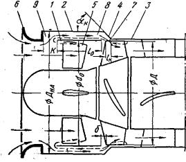
Fig.1.
Air separator scheme
The basic stream
moves through the guide-vane grate and partly sucks through channel 8 towards rotor
wheel at fan work of on antistall modes. Flow rate in channel 8 becomes close
to zero at the optimum mode. At the further fan productivity decreasing swirling
flow begins moving in direction from rotor wheel through channel 8. The
disturbed flow goes out through passage-way 9 and unites with basic stream.
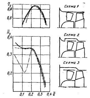
Fig. 2. Characteristics
of fan К-9Г-12 at work with separator and without it
On a fig. 2 the
characteristics of fan К-9Г-12 are shown at work with inlet collector and without separator (scheme
1), with inlet collector and air separator (scheme 2), with circular ledge and
air separator (scheme 3). Characteristic comparison shows that in the range of
the modes ![]() = 0, 21- 0, 36 application of separator with inlet collector
results the decline of pressure and coefficient of efficiency approximately on
1% (compared with scheme 1). At
= 0, 21- 0, 36 application of separator with inlet collector
results the decline of pressure and coefficient of efficiency approximately on
1% (compared with scheme 1). At ![]() < 0, 2 separator provides removal of trough and considerable
efficiency factor increase. Pressure characteristics at fan work on schemes 3
and 2 coincide practically [4].
< 0, 2 separator provides removal of trough and considerable
efficiency factor increase. Pressure characteristics at fan work on schemes 3
and 2 coincide practically [4].
The antistall
device of axial fan has the defect, that shells are located on the greater
diameter of flowing part, which substantially decreases the plane for air flow,
increases hydraulic resistance and decreases the axial fan productivity and
piles the construction of axial fan in whole.
It is possible to
remove this defect if make the antistall device in a form vanes, set between the vanes of guide-vane,
which will decrease hydraulic resistance of flowing part, will increase plane
for air flow and will increase the axial fan productivity [5]. On fig. 3 it is
represented antistall device of axial fan, in form of vanes 1, set between vanes
of guide-vanes 3.
There is vortex,
which hinders the motion of air and decreases the fan productivity at rotor
wheel rotation, especially at large charges in gap between guide-vane and rotor
wheel.
The axial fan device
works like this. Vanes 1 are executed
in thin plates form, the chord of which is equal to 0, 4 from the chord of
guide-vane, and height – 0.4 from its height. Such vanes localize the areas of
reverse currents and simultaneously untwist them in axial direction. It results
in the substantial weakening of co-operation of basic and reverse streams,
removes the stall areas along guide-vane.
It prevents the stall of flow that conduces
diminishing of hydraulic resistance of fan flowing part, increases the plane of
flowing part and promotes the axial fan productivity.
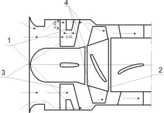
Fig.
3. Antistall device of guide-vane of axial fan
Analogical method
can be applied to the rotor wheel (fig. 4). Here the antistall device is done
also in form of thin bent plates [6], angles of inlet and outlet of which
coincide with streamline, the chord of plates is equal 0,4 from the chord of vane
of rotor wheel, the height of plates is equal 0,4 from the height of vanes of rotor
wheel. Such construction of antistall device, as well as in previous case, decreases
hydraulic resistance flowing part of axial fan, increases the area for basic
stream and increases the fan productivity, prevents stream stall on vanes 4 of
rotor wheel 2, which decreases hydraulic resistance of fan flowing part,
increases the plane of flowing part and raises the axial fan productivity.
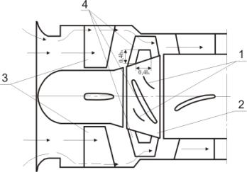
Fig.
4. Antistall device of driving wheel of axial fan.
We will underline
once again, that shown structural solutions increase the plane of flowing part,
decrease the hydraulic resistance and increase the axial fan productivity
comparing with air separator.
References
1.
Экк Б.
Проектирование и эксплуатация центробежных и осевых вентиляторов/ Экк Б.-Москва.: ГОСГОРТЕХИЗДАТ, 1959, 566с.
2.
Центробежные
вентиляторы. Под ред. Т.С.Соломаховой. М.: Машиностроение, 1975, 416 с.
3.
Брусиловский
И.В.. Аэродинамика осевых вентиляторов/ И.В.Брусиловский. - М.: Машиностроение.
1984, 238с.
4.
Пак
В.В., Иванов С.К., Верещагин В.П. Шахтные вентиляционные установут
местногопроветрвания/ В.В.Пак, С.К.Иванов, В.П. Верещагин.- М.: Недра, 1974. –
240 с.
5.
Патент України
на корисну модель № 25366. МПК F24F 7/06. Противозривний пристрій осьового
вентилятора / В.М. Башков, Н.Д.. Андрійчук, В.В. Бикодоров, А.О. Коваленко,
Ю.В. Бараніч, Є.С. Гусєнцова, В.І. Соколов, І.К. Насонкіна, І.В. Щурова. - № u 2007 02388; Заявл. 05.03.2007; Опубл. 10.08.2007. Бюл. № 12.
6.
Патент України
на корисну модель № 25460. МПК F24F 7/06. Противозривний пристрій осьового
вентилятора / В.М. Башков, Г.В. Андрійчук, В.В. Бикодоров, А.О. Коваленко, Ю.В.
Бараніч, Є.С. Гусєнцова, В.І. Соколов, І.К. Насонкіна, І.В. Щурова. - № u 2007 03434; Заявл. 29.03.2007; Опубл. 10.08.2007. Бюл. № 12.
7.
Осенин
Ю.И. Аэродинамика проточной части охлаждающего устройства тепловоза/ Осенин
Ю.И., Гусенцова Я.А., Сорока С.И.-Луганск: из-во ВНУ им. В Даля, 2012. – 162 с.