Techniczne nauki
Nickolay Zosimovych1, Vira Mazur2
1Sharda University
(India, UP)
2National Aviation
University (Kiev, Ukraine)
DESIGNING
COMPUTER ANALOG OF HEAD-UP DISPLAYS IN CONTROL OF UAV
Summary. In this paper studies the
task based on structural and parametric designing
method considers the technique of
design an analogue computer display on a
windshield as a main indicator
in the system of unmanned aerial vehicle
ground control complex. Shown evaluation of
current and prospective items
when selecting a constructive solution.
Key words: an analogue computer
display on a windshield (ACDW), display on a
windshield (DW), unmanned aerial vehicle (UAV), flying vehicle (FV), structural and
parametric design, cathode-ray
tube
(CRТ), indicator of the
situation in vertical plane (ISVP).
Introduction. The computer analog display
on a windshield (ACDW) may be a key indicator of UAV various applications [1]. By the principle of it belongs to the class of projection optical indicators
with a projection of piloting, the survey, navigation and supporting information on the computer analogue of FV windscreen - semitransparent
screen, through which at the same time
observed the space of behind a cabin. Combining images
on one screen - integration of information
allows to reduce the workloads an operator and UAV
establish normal operating conditions
of the visual analyzer since is not required next [2]:
1. Moving glance
at devices and search for the
appropriate device.
2. Refocusing (changing
accommodation) of the various objects.
3. Changing (change
adaptation) on the field of view different
illumination.
Problem statement. Computer analogues
of DW can be
divided into such [3]:
1. Electromechanical
and electro-optical (by methods of imaging).
2. Analog
and digital (by control methods).
3. Refractive and
reflective type (by structures of the
optical system).
4. Conventional and
diffractive (holographic) by type of optical elements.
Currently most widespread the electro-optical
DW due to simple
construction and ease of operation [4].
The structure consists of the
following blocks of ACDW:
1.
Of image formation.
2. The
indicating with power supply.
3.
Control.
The basic
element of the structural and parametric design the
imager is a symbol generator in which is recorded the program painting symbols as
letters, numbers, scales, geometric shapes, vectors, etc. The program of painting
tends to
implement the so called bar (italic) method,
when forming a beam
paints the symbols on screen like a pencil
on a paper.
For imaging of onboard survey
systems (television, infrared, radar)
may be on a television screen. For
obtaining a combined image and symbolism of survey
system can be use a mixer image.
Display console includes
a projection cathode-ray tube (CRT) with very high brightness of the screen [4]. Basic element of optical imaging
system is a collimating system,
which provides reproduction images from a
projection CRT in the
imaginary infinity that excludes parallax between the
external (behind a cabin), real
situation and symbolism generated
on the screen of the tube, and requires
no changes focusing (change of
accommodation) view, which is
necessary when observed objects
deleted at various distances from the
eye.
As a collimating lenses system are used, well as diffractive (holographic) optical
elements (ACDW diffractive) [5].
At the diffraction ACDW as windscreen used an analog diffractive
optical element. The control unit enables
automatic controller ACDW screen
brightness and the mode switch [2].
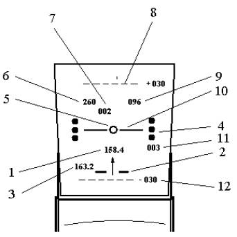
Fig. 1. The scheme of indicating on the windshield [2]: 1 – assigned course; 2- sliding; 3 – course; 4 – indexes the angle of attack; 5 – UAV (FV) index; 6 – the indicator’s speed; 7 – speed error; 8 – the pitching line +300; 9
– altitude; 10 – skyline; 11 – vertical speed; 12 – the pitching line -300
The final recommendations for type and
volume of appears on ACDW symbolism still are not
developed and therefore each developer offers
its own interpretation [3]. However, in different
stages of flight required on the display the
character representation in the
form of an aircraft rolling silhouette to move you’re according
to the evolutions of the angles of attack
and glide, roll, and pitch [6].
Increase field of
vision along the vertical can be
reached due to installation of two or
more head-shields
placed on the ACDW one after
another and which
give two or more images. If properly imaging is
obtained integrating this increase in the
total vertical image [2].
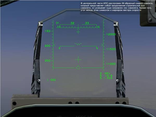
Fig. 2. The display view on the windshield ACDW for UAV
For structural and parametric representation information
about course is used horizontal scale with a
movable label, and the
vertical scale is used
to represent the information about vertical
speed and altitude [7]. There may also be
displayed on the screen such UAV parameters, as indicated
air speed and
director semi-automatic control (Fig.
1).
The analysis of results. Increase field of
view may be partially accomplished
by using the effect of binocular vision, which
always exists in a horizontal plane. Using in ACDW diffractive (holographic) element (Fig. 2)
with the given optical properties allows excluding a bulky and expensive
collimating lens [6].
The main characteristics of DW given in Table
1.
The indicator of the situation in
vertical plane (ISVP) is used for displaying synthesized image the real
picture of surrounding area with
distinct horizon line,
focusing on which an operator can pilot the UAV as the usual a visual flight.
Table 1
The main characteristics of DW [3]
|
Characteristic |
DW a
refractive optical circuit |
ACDW a
diffractive circuit |
|
Fields of view both
horizontally and vertically, degrees |
170 х 11,5 |
350 х 20 |
|
Luminous transmittance |
70 % |
90 % |
|
The light reflection coefficient |
25 % |
80 % |
|
Brightness of symbols, cd/m2 |
5400 |
17000 |
|
Brightness of the
bitmap, cd/m2 |
1300 |
4000 |
|
Accuracy of symbols (mrad) |
2,0 – 2,5 |
0,6 – 1,0 |
|
The mass, kg |
15 – 18 |
10 |
Furthermore the
quality information on quantitative
values of the derived ISVP basic flight parameters
(roll, pitch, airspeed,
etc.) for all phases of flight: takeoff,
climb, en-route, and landing. On the
basis of that information operator
receives an idea of the
spatial position of UAV and its
trajectory. ISVP is also used for structural
and parametric representation of
information-board survey radars,
infrared systems, and television, including with
imposing piloting synthesized symbolism.
As a flight director display overlap
with the responsibilities ISVP ACDW, but also enables greater
opportunities for output to information
display on-board survey systems
and to have TV ahead an image laying space with
which to implement the
takeoff and landing.
In order to color code can be
recommended the following distributions
of colors: green - motionless scale;
yellow - alarm warning; blue - fixed signs,
sky; red - alarm,
prohibitions; bright red - sample numerical
values and symbols; white - the
current value of parameters and symbols;
black - the background,
the negative image.
In structural and parametric
representation of information on ISVP an
increasingly observed switching
to graphic picture of uniform
presentation, best perceived the
operator of UAV, which contributes
to the development of digital technologies. The
foundation was laid in the pseudo indication
of a perspective view of the
so-called "Road
to the Sky" [3], the
movable far end of which allows
predicting the position of UAV. On the «Road»
are applied transverse lines which characterize the range intervals. The
further development of picture indicating a representation moving
images in real time by using high
complexity symbols the forms
and color coding [5].
On the indicator submitted three
dimensional perspective of the
cockpit form on which such a line of black, specified projected
onto flight path («Road to
the Sky»), and information about the
spatial position shown changing
of position UAV respect
to earth surface (Fig. 3). Information
about the restricted areas appears as dome-shaped zones, dyed red.
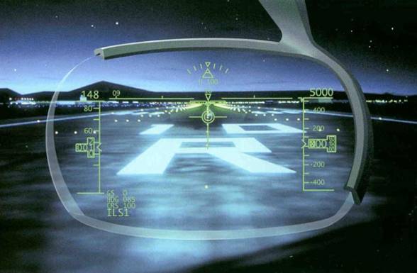
Fig. 3. Three-dimensional perspective indication on the windscreen DARPA of UAV
The formation of moving image of indication with high
complexity forms from the large
number of elements in real
time requires the development of generating images,
processes and related hardware,
allowing obtain images from 40000-400000 elements with
frequency over 40 Hz [8, 9],
significantly higher than of existing display
systems, in which moving objects
can be represented basically just by
conventional symbols.
Conclusion. Based on the structural
and parametric design method
considers the technique of designing
an analogue of computer indicator on the windshield in the system of ground control complex
the unmanned FV. Demonstrated
the assessment of the existing and future items the choice a
constructive solution.
References
1. http://shkolazhizni.ru/archive/0/n-36539/
- А вы знаете, что такое Head-Up Display?//
Школа Жизни.ру. Познавательный журнал.
2.
Зосимович Н.В., Котков В.И. Методика отображения информации в комплексе
БЛА для оперативного природоресурсного и экологического мониторинга окружающей
среды // Збірник
наукових праць до IV
науково-практичної конференції «Сучасні проблеми збалансованого
природокористування», листопад, 2009.– Кам’янець-Подільській: Подільській
державний аграрно-технічний університет, 2009. – С.150-153.
3. Зайцев
А.Г., Титков О.С. Проектирование информационно-управляющих полей кабины
авиационных комплексов./ Учебное пособие. – М.: МАИ, 1983. – 55 с.: ил.
4.
Проблемы
разработки кабины экипажа самолетов. – ЦАГИ: Техническая информация.- 1982.- №
3.
5.
Построение системы изображения информации
современных самолетов (обзор). – ЭИ Авиастроение.- № 7.- 1979.
6.
Зосимович Н.В., Котков В.И. Компоновка информационно-управляющего поля наземного
комплекса управления ДПЛА // Сборник трудов по материалам международной
научно-практической конференции «Перспективные инновации в науке, образовании,
производстве и транспорте ‘2008». Том 3. технические науки. – Одесса:
Черноморье, 2008. – С. 16-22.
7.
Зосимович Н.В. Проектирование информационно-управляющих полей наземного комплекса управления ДПЛА для оперативного
природоресурсного и экологического мониторинга окружающей среды // Малий і середній бізнес
(Право, держава, економіка). – К.: НАУ, 2008. - № 1-2. – С. 323-330.
8.
Технологии разработки программного обеспечения./ С.А.
Орлов. – СПб.: Питер, 2004. – 527 с.: ил.
9.
Fenton, N.E., Pfleeger S.L. Software Metrics:
A Rigorous & Practical Approach. 2-nd Edition. International Thomson
Computer Press, 1997. - 647 pp.