Lavrenko Ia., Babenko A.
National technical
university of Ukraine «Kievsky
politechnical institut», Kiev, Ukraine
The lifetime
research of laboratory centrifuge
To the high-speed
laboratory centrifuge is put forward a number of requirements, the main one is
to provide the necessary lifetime, the second, the guaranteed service life
should be ensured fail-safety and reliability. These requirements are satisfied
by the elements of data structures must not break down during the guaranteed
period of work and safety is guaranteed by the presence of emergency shell [1].
Laboratory
centrifuges are used in medical, biomechanical and in chemical laboratories.
The main tasks of design is to ensure reliability, capacity and ease of use.
Because of the different conditions of operation, the industry supports a wide
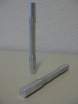
range of rotors and adapters for laboratory centrifuges (Fig.1). The rotor (I) of lab centrifuge
|
|
|
Fig. 1. Rotor and cap of lab
centrifuge |
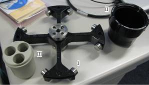
which
rotates is one of the most loaded constructive elements who use at variable
loading is destruction represents danger. The cup (II) with different forms for
beakers (III) fixes on pins and changes the position at speed up and speed
down. During the investigation it was found out that the
destruction takes place cups in place of contact with pins, and through
detachment bottom of the cup [2]. Structural elements, which is the danger of
destruction, is a cup.
In this paper the
cups as one main constructive element is mounted to a laboratory centrifuge
rotor, Figure 1 was
considered. To improve the accuracy of predicting the lifetime
of the machine and, consequently, more accurate selection of the parameters of anti-crash container in order to facilitate their weight. To
predict the lifetime of constructive elements, it is necessary to determine more
accurately their stress-strain state (SSS) and mechanical properties of the
material structure.
The
lifetime of construction can be defined as experimental and simulation course.
Actual testing of the acceleration and braking of centrifuge take a
lot of time and are expensive, so to predict the construction resource the
simulation of stress-strain state (SSS) centrifuges at different types of loads
and complex of experimental studies was carried out. In this case, the dynamic
calculations are performed by FEM [3]. Definition of
the stress-strain state made within the collaborative work NTU "KPI"
and the Institute of Mechanics, Otto-von-Guericke University Magdeburg
(Germany) by means of widespread software package ANSYS [4, 5]. The maximum stresses and deformations which
arose in a cup under the influence of a cup body weight were considered first
of all. Identified three levels of stresses (470 MPa, 490
MPa, 500 MPa), which arise in dangerous points of cups lab centrifuge. To determine the influence of stress concentration the parameter which is called as theoretical
coefficient of stress concentration is used [6,7].
|
|
|
|
|
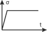
Fig.2 Cyclic load |
Fig.3 Cyclic creep |
Fig.4 Creep |


To the test used
hydraulic test stand MTS 810 (Fig.5). Mechanical properties of samples were
determined by their stretching with speed of 10 mm/min. Tests made according to GOST 1497-84.
The character of deformation studied on diagram points according to the methods [8].
|
|
|
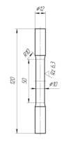
Fig.5 Samples and test stand MTS 810 to determine the mechanical
properties of materials |
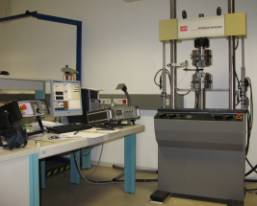
To
the test used hydraulic test stand MTS 810 (Fig.5), through which conducted
three phases of research. In the first phase of research were tested
cylindrical specimens of aluminum alloy 7075 on low cycle (Fig.2) with sawtooth
cycle fatigue loading (loading sample to the required level of stresses
occurred at 5sec and unloading 5sec). In the second phase were tested at
constant load to fracture (Fig.4). Laboratory centrifuges work in different conditions,
therefore the time the centrifuge is in the operating conditions could be
different. In this paper, the time ![]() chosen on the basis
of the optimal time of testing samples. The third phase of testing - the study
sample at program load (Fig.3) (load sample 5sec, holding at constant load
120sec and unloading 5sec).
chosen on the basis
of the optimal time of testing samples. The third phase of testing - the study
sample at program load (Fig.3) (load sample 5sec, holding at constant load
120sec and unloading 5sec).
|
|
|
Fig.6 Specimens failure probability 1% |
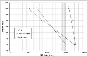
Plot
the fatigue curves was performed by the standard method according to GOST [9, 10].
On the basis of the distribution curves of fatigue life curves of equal
probability was built. At the diagrams curves of fatigue specimens of aluminum
alloy 7075 for the probability of destruction ![]() are shown. Fig. 6
shows the fatigue curves for different types of loading at a probability of 1%.
It can be concluded that the maximum lifetime have specimens that tested at low-cycle
fatigue.
are shown. Fig. 6
shows the fatigue curves for different types of loading at a probability of 1%.
It can be concluded that the maximum lifetime have specimens that tested at low-cycle
fatigue.
Conclusions
Researches
have shown that the unsuccessful choice of manufacturing techniques of
preparation is one of the reasons which promotes destruction in the form of
branch of a bottom of a the cup shell. In all cases the stress-strain state
simulation has shown that the maximum stresses take place in a point of contact
of a pin of a rotor and cups of a laboratory centrifuge. It leads to cup
destruction in a place of contact of a pin and a cup.
As a result of
experimental studies were built durability and fatigue distribution curves for
aluminum alloy 7075. These data allow to conclude a satisfactory correlation of
experimental and theoretical calculations. The approach proposed by Lemaitre
counting of interaction damage under cyclic creep gives satisfactory results,
but requires further research.
References
[1] Lemaitre J.,
Desmorat R. Engineering Damage Mechanics, Springer, 2005, p.380.
[2] Babenko A., Lavrenko Ia., Strackeljan J. Estimation
of a centrifuge rotor strength and analysis of the influence of constructive
and technological parameters. // 10. Magdeburger Maschinenbau-Tage. 27.-29.
September 2011.
[3] Babenko A., Lavrenko Ia. Vyznachennja napruzheno-deformovanogo stanu
chashky laboratornoi centryfugy pid dijeju dynamichnogo navantazhennja. //
Vseukrainskyj shhomisjachnyj naukovo-tehnichnyj i vyrobnychyj zhurnal.
Mashynoznavstvo. – L.: - 2011. - №7-8. - s. 7-10.
[4] Lavrenko Ia. I. Do pytannja
pro vyznachennja resursu konstruktyvnyh elementiv pry zminnyh navantazhennjah.
Visnyk NTUU “KPI”, Mashynobuduvannja. - K.: Yzd-vo KYT, 2009 . - №. 56.,
s.88-92.
[5] Stolarski
T., Nakasone Y., Yoshimoto S. Engineering Analysis with ANSYS Software, 2006.
[6] Neuber
H and Hann H. Collection of Translations, Mechanics, №4, 1967.
[7] Pisarenko G. S. Strength of materials - 5th ed. Rev.
And add. - K.:
Highest sc. Head Press, 1986.
[8] Pavlov I. M.,
Shelest A.E., Tarasevich Y.F. The study of discontinuous deformation patterns of
some alloys after thermomechanical processing. - In Sat: Plastic
deformation of refractory metals and special alloys. Nauka,
Moscow, 1970, p.111-125.
[9] GOST 28785-90
«Ultracentryfugy ta rotory preparatyvni. Zagalni tehnichni vymogy ta metody
vyprobuvan».
[10] GOST 25.502-79 «Metody mehanichnyh vyprobuvan
metaliv. Metody vyprobuvan na vtomu».