RESEARCH
STRENGTH OF INDIRECTLY-REINFORCED BEAMS ON AN INCLINED CROSS-SECTION PRODUCED
BY LLP “BINOM”
E. Seidullayev, K. Ermuhanov
Currently, the indirect
reinforcement of concrete is mainly used to increase the strength of the compressed
elements with concentrated loads of action (local compression of the end cap
columns near the joints, anchoring zone pre stressed reinforcement). The
contribution of indirect reinforcement to increase the bearing capacity of the
element is evaluated given concrete compressive strength![]() , defined
by the formula (48) SNIP 2.03.01-84 *.
, defined
by the formula (48) SNIP 2.03.01-84 *.
The aim of our experiments was to determine the effect
of lateral reinforcement for the maximum transverse force perceived bendable
concrete elements on the inclined cross-section at their destruction. To
achieve this goal it was necessary to achieve the following objectives: to
develop a test method; perform tests of prototypes with different percentages
of indirect reinforcement for the determination of the maximum lateral force
and indirect contribution to the reinforcement of load-bearing capacity;
identify the features of the effect of lateral reinforcement in the elements of
the value of the bearing capacity and the nature and form of the destruction of
the inclined sections; experimental set limit transverse force perceived
bendable concrete elements on the inclined cross-section, at various ratios of
lateral reinforcement.
Test samples were divided into 2
groups for the study of the various factors influencing the marginal transverse
force perceived sloping sections. The first group consists of two cross members
- the twins (TAA TAA-1.1 and-1.2) with a transverse reinforcement - grids with
a pitch of 70 mm in the form of wire mesh package of Ø3Vr-I and
Ø4Vr-I. In the second group also ravine - the twins (TAA TAA-2.1
and-2.2) with a transverse reinforcement grids as a package with a pitch of 50
mm wire Ø3Vr-I and Ø4Vr-I. In all samples the stretched zone
reinforced rods 2Ø12 A-III. Dimensions prototypes (Table) were due to
the limitations of the test equipment availability. The objectives of the
research group 1 is to get the results of the indirect effect of reinforcement
on the bearing capacity of the inclined cross-section of the joint action of
the bending moment M and shear force Q. The objectives of the research group 2
are to get the results of the effect of lateral reinforcement on the strength
of an inclined cross-section by the action in the main transverse force Q. In
samples (with the subscript "a"), the transverse reinforcement in the
form of grids is substituted minor diameter C-2 provided in the zone of
formation of cracks inclined bent elements.
Grids lateral reinforcement can be
welded of the intersecting rods, while on the requirements of building
regulations must observe the following conditions: a) cross-sectional area
of rods (wire) grid on the unit of
length in one direction and the other should not differ by more than 1.5 times;
b) a step grid (distance between the grids in the axes of the rods in one
direction) are taken at no more than 1.3 of the element section and not more
than 150mm; c) in the grid mesh size assigns light at less than 1.4 of the
element section, and not more than 100mm.
To prevent the destruction of the
inclined sections of the action of the time and on the support for reliable
anchorage of longitudinal reinforcement to them were welded cross bars with
10mm diameter 5cm step in the area of the anchorage.
The prototype test was
carried out according to the scheme of four - point and three-point bending.
Before tests on each beam installed cargo distribution plate 75x150x10mm.
Driving test major series of beams is shown in Fig. 1, a general view of the
experimental setup in Fig. 2. In all the basic series to prevent the influence
of the two thrust bearings were adopted hinge-movable.
In tests of all samples
was used the equipment brand "ZIM" (type: R-50, GOST 8905-93). The
app load was carried out in steps of 15-20kN, which corresponded to 1/5 (20%)
of the projected breaking force. The magnitude of the load is controlled by
indications silo meters corresponding test equipment.
|
Sample
mark |
b |
R |
Rb |
Rbt |
|
Driving
test |
Fexp |
Fснип |
Fexp/ Fснип |
|
ТАА-1.1 ТАА-1.1а |
75х150х135 |
В26.4 |
21.05 |
2.06 |
0,0180 |
|
76,8 68,1 |
64,48 58,81 |
1,191 1,158 |
|
ТАА-1.2 ТАА-1.2а |
0,0102 |
76,53 67,4 |
64,48 58,81 |
1,187 1,146 |
|||||
|
ТАА-2.1 ТАА-2.1а |
0,0252 |
|
109,4 |
90,21 |
1,213 |
||||
|
87,6 |
74,5 |
1,176 |
|||||||
|
ТАА-2.2 ТАА-2.2а |
0,0142 |
108,8 |
90,21 |
1,206 |
|||||
|
86,9 |
74,5 |
1,168 |
The sequence of formation of cracks in all test samples
was essentially the same: first, in the tension zone of the beams appeared
normal - torque, then inclined crack of shear force. The development of cracks
as loading and forms of destruction of samples vary greatly depending on the
percentage of transverse reinforcement. Along with common features, each group
of prototypes and were especially fissures of transmitted load and the nature
of the forms of destruction.
The destruction of all the samples as
expected, did not differ from the destruction of the inclined beam cross
section under the action of concentrated loads, ie, identical as in earlier
experiments conducted by other authors. The final destruction of the sample
came with large opening inclined cracks. Dependence of the strength on the
inclined cross-section of the lateral reinforcement ratio is shown in the
figure:
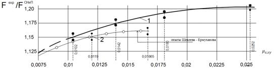
Fig.2. The
dependence of the strength on the inclined cross-section of the lateral reinforcement
ratio
Based on the results of the pilot study,
the following conclusions:
1. Indirect
reinforcement at the reference length (s) of the span bent elements (ie
replacement clamps on the grid of small diameter), resulting in a substantial
increase in the bearing capacity of the inclined cross-section of the joint
action of the moment and shear force.
2. Indirect
reinforcing a positive impact on the strength of compressed concrete zone, ie,
increases given prism strength of concrete compressed zone of the inclined
crack of a flexible element.
REFERENCES:
1. Zalesov A.S., Klimov Y.A. Durability of reinforced concrete
structures under the action of shear forces. Kiev. : Budivelnyk, 1989.-241p:.
Il.
2. Innovative patent №27350. Reinforcing cage of reinforced concrete
products (auth. Ermuhanov K.E., Shekeev D.B.).
3. Shekeev D.B. The strength of concrete beams on an inclined section. Magist.
thesis on competition of acad. Master degree of tehn. sciences at M. Kh. Dulatiy TarSU,: Taraz, 2015.
4. GOST 14098-91 Welded joints of reinforcement and inserts
manufacturing of reinforced concrete structures. Types, design and dimensions.