Raul Rink1, Dr. Sergey Shestakov2
1Oil Tech Production OY, Estonia, 11913, Tallinn,
Kressi Tee, 34 A,
E-mail: info@oiltech-nordic.eu
2Moscow state university of Technologies and
Management, Russian
Acoustical Society, Russia, 109004, Moscow,
Earth wal, 73,
E-mail: sdsh@mail.ru
The Cavitation Reactor with Symmetric Solid-State Oscillatory System of
the Acoustic Cell for Processes of the Food Sonochemistry
In
comparison with well-known, describes in the technical and patent literature
counterparts acoustic cavitation reactors suitable for use in food
sonochemistry, consider examples of the executed on the basis set forth in the
[1] of theoretical bases of projects reactors, mastering the production of
which started in Estonia and prepared in the republic of Belarus. They are
intended for physic-chemical treatment by ultrasonic cavitation true and
colloidal solutions, as well as disperse systems (emulsions and suspensions) by
initiating in them the sonochemical reactions and cavitation erosion of their
phases. In addition to these solutions, emulsions and suspensions in these
reactors can be processed chemically pure water and other chemically pure
solvents. In them is the impact on their
physical-chemical state of liquids, the intensification of in them chemical
reactions and initiation of new by changing the dipole-dipole and ion-dipole
interactions in their environments and phases, as well as increasing the
dispersion of multiphase systems, the destruction of bacteria and stabilization
of their number.
A typical example of a well-known classical design of
the reactor is, for example, a device, patented in the united states for nearly
half a century ago, and is called the "vibrations device" [2]. It is
equipped the reflecting wall, mounted so that his surfase is aimed in the
liquid, is in one plane with the surface of ultrasound radiator, surrounding
it. That is, surface of the front of ultrasonic wave, containing surface of the
radiator, coincides with surface of the wall, which has contact with liquid. The
second of reflective wall, located opposite first and radiator in the direction
of propagation wave is part of the corps of reactor. But the energy of
cavitation is the cause of erosion fracture of solids [3]. Erosion may be
subjected the structural elements design of cavitation reactor. The products of
erosion, falling in the treated liquids, can irreversibly change its physical
and chemical properties, which are strictly not allowed in the processing of
medicinal and food raw materials, as well as the medical products and food
products.
Housing this device is exposed to cavitation erosion,
caused by his contact with the perimeter of the cavitation areas, which related
to it work [4]. In addition, because the reflective the wall which is lying
opposite the radiator is part of the hard corps, it not may fully reflect the
elastic wave and its fluctuations partially transmitted the on the corps, which
leads to energy losses. The surface of the radiator and the walls are exposed
to erosion under the action of cavitation, which occurs near them.
Known the analog of reactor, consisting from a working
camera (the corps), the source of ultrasound
for creating cavitation and reflective wall, between which is placed
elastic layer, absorbing penetrating part of the ultrasonic wave and turns its
into heat [5]. In such a device rigid mechanical connection between reflective
wall and the corps is absent, which allows you to dissipate some of the energy
of ultrasonic waves in the film between them, and prevent the dissipation of
the energy of elastic waves on the cavitation near her. However, here, as in
the previous case, the walls of the corps are exposed to cavitation, formed in
the volume of fluid. Cavitation near the sides of the corps causes erosion of
the metal from which it is made and the ingress of its ions in the work
environment, which prevents the use of a similar reactor in the field of food
sonochemistry.
There is the design
of the cavitation reactor, representing a camera, the volume of which is
limited surface wall of corps, at least one of the reflective wall, at least
one emitter of acoustic waves and is filled with in the work the treated
liquids [6]. The size of the corps in the plane of any front of the elastic
wave is equal to the minimal positive root of a transcendental equation,
obtained by equating to zero singular generalized function, which approximates
the function of the integral of a dimensionless stiffness [4]. The root of this
equation determines the size of the housing, in which the potential energy
density of the cavitation at its surface is equal to zero. That is the erosion
of the walls of the corps in such a reactor is completely excluded. However,
the surface of the transducer ultrasonic waves still exposed to erosion, since
cavitation on its surface occurs because of the difference of the
amplitude-phase characteristics of radiated and fall on him the wave reflected от opposite wall, about the means and ways of
equalization of which in the description of this reactor nothing no.
Known similar in
design cavitation reactor [7], where made the alignment by the largest
vibration amplitudes of fluids near reflective walls and these walls by
selection the acoustic resistance of the absorbing material layer between them
and the housing. This allowed to avoid cavitation also have the radiator
surface of ultrasonic waves and thus exclude it erosive destruction. But this
reactor also has the disadvantage of preventing its use for the treatment of
liquids in the food processing industry. The alignment of the amplitudes of the
oscillations of a radiator and reflecting walls and liquid near them here
achieved through the organization the regime, such as energy regime of
traveling wave, when the whole falling on the wall of the wave passes through
it, are not reflected back inside the reactor. The wall is here called
reflective only conditionally. A portion of the energy of wave which
transmitted through the wall into layer between her and the corps, scattered on
the internal friction of the material from which made this layer. And only part of the energy transferred by a wave
from the emitter to the treated liquid will be dissipated in it on cavitation.
Thus, the exclusion erosion of the material reactor is achieved here due to
the loss of part energy of the wave
radiated in the fluid of its source. For this additional costs are required
energy, replenishes these losses. And diffused in the layer between wall
and the corps the energy is converted into heat, which is gradually heats up
liquid, lowers threshold of cavitation and intensity of the latter [2]. This is
partly remedied in the acoustic cell cavitation reactor, where reflective wall
is regarded as an integral part of oscillatory system from the source of the
waves and located in this cell the fluid [8]. It is a solid-state mechanical
element with zero reactive components of acoustic impedance and high mechanical
q-factor. This allows to avoid thermal scattering, as the power, the equivalent
to dissipated on the internal friction, with her help of is transformed into a
reactive power, which can be compensated on the electrical side included in the
source of ultrasound electro acoustic transducer, which is acoustically
connected with the liquid and reactive sonoabsorber in the one oscillatory
system. But still, a part of this system
draws part of the oscillation power into the reactive power, that is, brings it
out the cavitation process in the other part of it - in the liquid, for whom,
and there is a cavitation reactor.
Such disadvantage is absent in the other
reactor, where all the parts of the vibrating system of acoustic cell is
solid-state [9]. In its design the surface to facing the transducer reflective
wall and itself emitting surface
belongs to the general solid-state resonator with resonance frequency equal to
the frequency of fluctuations of a radiating surface and posted near antinodes
of vibrational displacement, located between them fluid at a frequency of
resonance of its fluctuations. With such a cell in principle are possible to
implement a resonant mode of operation together with a liquid. It is clear that
the wave energy dissipated on the cavitation is the maximum. However, in [9]
there are no requirements to the structures providing such a regime. There
installed the distance between the planes of the resonator with which the
oscillations propagate in fluid equal to the length of their waves in it. But
the distance between antinodes of oscillatory displacement of solid-state
resonator which are near them is specified equal to half of length of a wave in
the metal. That is, these surfaces are commit fluctuations in the fluid in
opposite directions. Using the method of summing up the oncoming waves, in
which acts a cavitation, as described in [10], we can calculate that in this
case the average on height of the reactor, the amplitude of the sound pressure
of the fluid in it will reach 87% from the average amplitude of the sound
pressure in each of the waves from these surfaces, if they escape into an
infinite half-space (see fig. 2). This is a
disadvantage, the main reason of which is that it created the conditions for
the resonance of the solid part of the oscillatory system of the acoustic cell
of reactor but conditions of resonance in the processed liquid is not provided.
Therefore, the power of a cavitation is not maximal possible, which are may be
get from these sources of fluctuations.
Considering the volume of
the processed in the reactor of the liquid, placed between the planes of the
solid-state resonator, with which in her emanate the fluctuations, as part of
oscillatory system the acoustic cell of reactor, you can create the optimum
conditions for the superposition of these oscillations. For such conditions the
formed near the antinodes of pressure of the total wave areas of cavitation [4]
will occupy a larger total volume of [1,10]. This can be done, given the
well-known fact [10,11], that is in the water flat-elastic wave gives able to
generate cavitation energy at a distance of not more than three half-waves, and
on the length of the half-wave fluctuations in metal (when the ends of segment
is fluctuate in opposite directions) fit about three half-wave of oscillations
of the same frequency in the liquid. That is, there is no sense to do the
volume of working chamber of the cell reactor length more than 1.5 length of
wave elastic oscillations in liquid, when the radiating surface are from each other by distance half wavelength fluctuations of
metal. Then the height of the acoustic cell (the distance between the radiating
surfaces) must be exactly equal to half the length of wave oscillations of
metal on the same frequency. Such conditions is easier to implement when the
solid part of oscillatory system of the acoustic cell is symmetrical about the center of mass, that is, the sources of
fluctuations (converters) are located on both sides of the volume of treated
water in the reactor. It is known [3] that the geometrically symmetric relative
to its center of mass of a system of elastic fluctuations holds better
resonance. Education cavitation erosion of radiating surfaces for it with virtually no will.
Using the
mathematical model of cavitation reactor and the principle of similarity of the
cavitation processes, described in the first chapter, can compare such a
reactor with a benchmark by arming the computer experiment. The Estonian
company "Oil Tech Production OY"
(Tallinn) made a reactor with two converters connected to one power supply
(ultrasonic generator) and doing of coherent oscillations [12], which form the
standing elastic wave by in the flow water through workspace. He is shown in
fig. 1 and consists of the camera body 1, which is made from the standard
seamless stainless steel pipes of the outside diameter 90 mm, a wall thickness
of 5 mm. Acoustic booster 2 with emitting the ends of a diameter of 79 mm,
such, as described in [13], is fixed in the casing with flanges 2 through the
seals with the help of studs 4. As the sources of fluctuations used converters
MPI 5050F-20L (5).
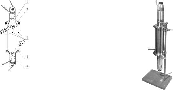
Fig. 1. Cavitation reactor of the
company Oil Tech Production OY,
described in [13]:
on the left is the design of the reactor;
on the right is a photo of the sample of the reactor, fixed on a
tripod.
|
Fig. 1. Cavitation reactor of the
company Oil Tech Production OY,
described in [13]: on the left is the design of the reactor; on the right is a photo of the sample of the reactor, fixed on a
tripod. |
As a
etalon was selected reactor, with a design similar to shown in the figure. 1.
This reactor is a reactor of a plane wave and is calculated by the formulas for
unsteady cavitation mode, since the time of its effect on the volume of the
processed water is very little for accounting of acoustic flows and under
hydrostatic pressure in it approximately equal to the atmospheric. Height of
the working chamber H standard (the distance between surfaces radiating the
coherent flat-elastic waves ) is selected to 1.5l in a liquid that has a static pressure ph = 1 atm,
the speed of propagation of flat-elastic oscillations c and density r close to the parameters of
chemically clean water (Fig. 2, a).
Total power consumption of radiators 2.4 kW.
Dimensions of the etalon chosen so that when consumed his converters of
electric power is the maximum amplitude of the sound pressure in the fluid
meets the concept of food sonochemistry. Through the working volume of the
reactor the fluid passes through the special nozzles.
The reactor,
with which made comparison (Fig. 2, b) contains a monolithic oscillatory system
of the acoustic cell, similar to the systems of the company Hielscher Systems
GmbH. The height of its single cell (the distance between the radiating
oscillations of the circular surfaces) is equal to two полуволнам in the liquid. It can contain a several of
such cells, components of total oscillatory system. The liquid in it passes
through the volume of the camera along the oscillatory system between it and
the wall of the chassis.
Reactors
UIP Hielscher Systems GmbH contain six cells, depicted in fig. 2, b, and source
- wave piezoelectric transducer is attached to the oscillatory system with one
side of her, as shown in fig. 3.
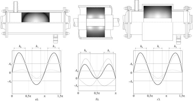
Fig. 2. a – design of the
etalon. The tonal pattern shows the distribution of the volume density power
cavitation erosion in the axial cross section; b – a fragment of a reactor
design firm Hielscher Systems GmbH.
Dimensions of working volume of a single acoustic cells are surrounded by a
dotted line; c –design of the reactor with a symmetric
solid-state oscillatory system of the acoustic cell. The tonal pattern shows
the distribution of the volume density power cavitation erosion. At the bottom
of figure on the charts shows the graphs of pressure:
▬ in emitted each
transformer waves, if they were distributed in an open half-space liquid;
▬ in the resulting wave of the
superposition of these waves. On the x-axis
shows the phase in radians at the resonant frequency of oscillatory system.
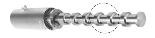
Fig. 3. Asymmetric
oscillatory system reactors UIP 4000 with a piezoelectric converter power
consumption 4000 kW in the housing
system of cooling (on the left).
Developed in accordance with the model [1] the reactor with monolithic
oscillatory system of the acoustic cell, the symmetrical about the center of
mass (Fig. 2, c), also consists of the camera body, maded from welded seamless
stainless steel pipes with a diameter 102 mm wall thickness of 6 mm and 146 mm
whis wall thickness of 7 mm, with a flanges with hole for fixing other flanges
with sealing by means of bolts and nuts (six on each side) waveguide
transformers with diameters of radiating surfaces 88 mm, which transmit the
vibrations sources (not shown) in the liquid with the a decrease of amplitude
and also interconnected barbell (Ø 32 mm) into a solid-state oscillatory
system. Compared reactors have a capacity of oscillation sources, the maximum
amplitude of the pressure of wave and the variance of the spatial distribution
of the power density of cavitation in the same as the etalon.
As a result of comparison were modeled performances for all these
reactors for the treatment of water used for the needs of food and
pharmaceutical industry, and pollutions her to the products of erosion in
relation to the indicators of the etalon reactor. Relative performance, so as
in all reactors used one and the same, the oscillation frequency f, is calculated as the ratio of works
average volume density of erosion capacity of cavitation in the working volume
of the chamber V
 (1)
(1)
where qer – volume density erosion power of cavitation
in point of space кавитирующей
fluid with coordinates x, a, y in
the volume V of the product the
indicators of etalon reactor:
 (2)
(2)
Instead of absolute
values of qer in the calculation of volumetric power density cavitation
erosion, because the liquid in the variants of one and the same, is used
contingent values:
 ,
(3)
,
(3)
where: a – the average of n cavitation areas of the
attenuation the total perturbations of pressure from all of the bubbles in the
point for which is calculated;
Svi = S×Shi – total volume of the i = 0...n cavitation areas (S - the
area of the front of the resulting wave in a reactor, equal to the square of
the surfaces radiating);
t
– average
of the dimensionless time of arrival perturbations of pressure from all the
bubbles n cavitation areas in this point;
 – amendment to the phase of the cavitation field. Square
brackets denote a whole, and curly - fractional part of the number. Lengths of the free run of
fluctuations of the pressure from cavitation for period of the harmonic wave
are equal to the length of the wave.
– amendment to the phase of the cavitation field. Square
brackets denote a whole, and curly - fractional part of the number. Lengths of the free run of
fluctuations of the pressure from cavitation for period of the harmonic wave
are equal to the length of the wave.
Dimensions hi
cavitation areas on the beam of the waves were calculated, as recommended
[1,10] in angular units phase as the diference between the values of the even
and odd positive roots of the transcendental equation:
![]() (4)
(4)
where: Аmax, А0 – the maximal amplitude of the sound pressure the
wave when the radiation of fluctuations doing in half-space of the liquid and
the threshold for the education of cavitation, respectively; h
– scattering coefficient of the energy of the waves on the cavitation [11]. In
the linear units, they were translated by dividing the on wave number 2p/l.
Water pollution the products of erosion calculated proportional to the integral
value volume density erosion power E
in contact with water metal surfaces of the reactors. For reference it is equal
to:
 (5)
(5)
and for compared
reactors:
 (6)
(6)
where: R2,
R1 – outer radius of
radiating surfaces and the radius of the connecting rod, respectively;
Н – the distance between the radiating
surfaces;
D – her diameter;
qer,1, qer,2, qer,3 – density
of erosion power of the cavitation in the points of the radius of a radiating
surface and in the points of rays are separated from the axis of symmetry at a
distance of diameter of the walls of the camera and the diameter connecting
rod, respectively.
The results of comparison in the values in relation to
the etalon shown in the table.
|
OPTION REACTOR THE
RELATIVE INDICATOR |
UIP (Fig. 2 b) |
Fig. 2 c |
|
The performance of water
treatment |
1,8 |
3,5 |
|
The variance of
the spatial distribution of the density of the power erosion* |
1,02 |
0,87 |
|
The erosion of
the elements of design |
2,5 |
3,9 |
*the variance was adopted as much as possible
close to 1.00.
From the table it can be seen that the reactor UIP 4000 which has 1,7
times more, than at etalon power consumption of the piezoelectric converter and
the same (slightly larger) the variance of the spatial distribution of the
density of power of the erosion in the
working chamber it has 1.8 times greater productivity of processing of water,
and 2.5 times larger erosion of the details of the construction. The reactor
with a symmetric oscillatory system acoustic cells with similar (slightly
smaller) the distribution of the density of power of the erosion in the chamber
has the performance in 3.5 times, and the erosion of the details of the
construction in 3.9 times higher than that of the etalon. In other words, the
change of these parameters is almost to proportion to each other. Thus, when
performing the above requirements to the size of the solid parts of oscillatory
system acoustic cell cavitation reactor his power of cavitation, performance
and cavitation erosion surfaces of the parts are increased proportionally,
which testifies to the fact that the absolute contamination of treated water
will not change, as it flows through the reactor proportionally faster, but
useless loss of energy elastic wave is reduced.
R E F E R E N C E S
1. Shestakov S., Babak V. // Applied Physics Research, V.4, No. 1, February
2012, pp. 64-77
2. Patent US 3519251, 1970
3. Knapp R., Daily J.
and Hammitt F. Cavitation.–NY: McGraw Book Company, 1970
4. Shestakov S. The
basic technology of cavitation disintegration.-M: EVA-Press, 2001 (in Russian)
5. Patent US 4618263, 1986
6. Patent RU
2209112, 2002
7. Shestakov S. et al.
// ХIII session of the Ross.
Acoust. Society, Vol.1 .- M.: GEOS, 2003, p.p. 31-35 (in Russian)
8. Patent RU 2392047, 2010
9. Patent ЕР 1810747, 2007
10. Shestakov S. and Befus
A. Dep. VINITI, 840-B2008 (in Russian)
11. Physics
and technology of high-intensity ultrasound / Rozenberg L. (Eds.), Moskow:
Nauka, 1968 (in Russian)
12.
Shestakov S. et al. // ХХIV session of the
Ross. Acoust. Society, Vol.2 .- M.: GEOS, 2011, p.p. 90-96 (in Russian)
13.
Shestakov S. // Х session of the
Ross. Acoust. Society, Vol.2 .-M.: GEOS, 2000, p.p. 115-119 (in Russian)